Biostar M7VIQ M7VIQ user's manual
Biostar M7VIQ Manual
 |
View all Biostar M7VIQ manuals
Add to My Manuals
Save this manual to your list of manuals |
Biostar M7VIQ manual content summary:
- Biostar M7VIQ | M7VIQ user's manual - Page 1
radio frequency energy and, if not installed and used in accordance with the instructions, may cause harmful interference to radio communications. There is no guarantee that for any mistakes found in this user's manual. All the brand and product names are trademarks of their respective companies. i - Biostar M7VIQ | M7VIQ user's manual - Page 2
: DDR1-2 4 Jumpers, Headers, Connectors & Slots 5 ESPAÑOL 12 Características del M7VIQ 12 Contenido del Paquete...12 Disposición del M7VIQ...13 Instalación del CPU ...14 Módulos DDR DIMM: DDR1-2 15 Conectores, Cabezales, Puentes y Ranuras 16 TROUBLE SHOOTING 23 SOLUCIÓN DE PROBLEMAS 24 ii - Biostar M7VIQ | M7VIQ user's manual - Page 3
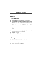
English M7VIQ Features Use Via KM266/ VT8235 Chipset, W83697HF, LAN Chip (optional). Contains on board I/O facilities, which include one serial port, one VGA port, a parallel port, a PS/2 mouse port, a PS/2 keyboard port, audio ports, USB ports, a LAN port (optional) and a game port. Supports the - Biostar M7VIQ | M7VIQ user's manual - Page 4
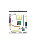
MMootthheerrbbooaarrdd DDeessccrriippttiioonn Layout of M7VIQ JKBMS1 JKBV1 1 1 JUSBV1 JUSBLAN1 JATXPWER1 JCOM1 JPRNT1 1 JDJ1 5 FDD1 FLOPPY DISK CONN. DDR1 DDR2 JCFAN1 1 JVGA1 GAME Port JSPKR1 SP-OUT JLIN1 LINE-IN JUSBV3 1 JMIC1 MIC-IN JAUD GAME LAN CHIP 2 10 19 Codec 1 1 1 JCODECSEL - Biostar M7VIQ | M7VIQ user's manual - Page 5
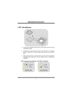
Pin A in the socket and lock for the white dot or cut edge in the CPU. Match Pin A with the white dot/cut edge then insert the CPU. 3. Press the lever down. Then Put the fan on the CPU and buckle it and put the fan's power port into the JCFAN1, then to - Biostar M7VIQ | M7VIQ user's manual - Page 6
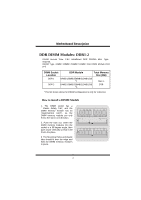
MMootthheerrbbooaarrdd DDeessccrriippttiioonn DDR DIMM Modules: DDR1-2 DRAM Access Time: 2.5V Unbuffered DDR 200/266 MHz Type required. DRAM Type: 64MB/ 128MB/ 256MB/ 512MB/ 1GB DIMM Module (184 pin) DIMM Socket Location DDR Module Total Memory Size (MB) DDR 1 64MB/128MB/256MB/512MB/1GB *1 - Biostar M7VIQ | M7VIQ user's manual - Page 7
mouse ports, keyboard ports and printer ports, this motherboard does not have built in video facilities; and therefore, requires a video card for one of the expansion slots. Your monitor will attach directly to that video card. Tis motherboard supports video cards for PCI, but is also equipped with - Biostar M7VIQ | M7VIQ user's manual - Page 8
Pin 7-8 on ==> 2.8V It strongly recommended to set DDR DIMM voltage in default setting 2.5V, and it for over voltage function. Wake On LAN Header: WOL1 Ground 5V_SB Wake up WOL1 Clear CMOS Jumper: JCMOS JCMOS1 Assignment 1 Normal Operation Pin 1-2 on (default) 1 Clear CMOS Pin 2-3 on Data - Biostar M7VIQ | M7VIQ user's manual - Page 9
1 +5V 2 +5V 3 Data (-) 4 Data (-) 5 Data (+) 6 Data (+) 7 Ground 8 Ground 9 Key 10 NA 5V/ 5VSB Selection for USB: JUSBV1/2/3 JUSBV1/2/3 Assignment 1 5V Pin 1-2 on 1 5V_SB Pin 2-3 on CPU Frequency Selection: JCLK1 1 JCLK1 On ==> 100MHz Off ==> 133MHz 7 - Biostar M7VIQ | M7VIQ user's manual - Page 10
MMootthheerrbbooaarrdd DDeessccrriippttiioonn 5V/ 5VSB Selection for Keyboard: JKBV1 JKBV1 1 Pin 1-2 on 1 Pin 2-3 on Assignment 5V 5V_SB CNR Codec Primary/ Secondary Selection: JCODECSEL J_CODECSEL Pin 1-2 1 Pin 2-3 1 Assignment On-board Primary Codec (Default). CNR Primary Codec. 8 - Biostar M7VIQ | M7VIQ user's manual - Page 11
IR 2 24 1 23 SPK HLED RST IR SPK ==> Speaker Conn. HLED ==> Hard Driver LED RST ==> Reset Button IR ==> Infrared Conn. SLP ==> Sleep Button PWR_LED ==> Power LED ON/ OFF ==> Power-on Button Audio DJ: JDJ1 1 5 JDJ1 Pin1 ==> SMBDT Pin2 ==> SMBCK Pin3 ==> -INTR_B Pin4 ==> NC Pin5 - Biostar M7VIQ | M7VIQ user's manual - Page 12
Out 7 Reserved 8 NC 9 LFT Line Out 10 LFT Line Out Pin 5 and 9 are routed to Front Panel Audio Out. Pin 6 and 10 are routed from Front Panel Audio Out. Front Panel Audio Connector/ Jumper Block Jumper Setting 12 3 5 7 4 6 Pin 5 and 6 Pin 9 and 10 9 10 1 3 5 246 No jumpers 7 9 10 - Biostar M7VIQ | M7VIQ user's manual - Page 13
MMootthheerrbbooaarrdd DDeessccrriippttiioonn Back Panel Connectors JKBMS1 RJ45USB1 PS/2 LAN(Optional) Mouse JPRNT1 Parallel JGAME1_USB1 Game Port/ USB Ports (optional) PS/2 Keyboard USB COM1 JCOM1 VGA1 JVGA1 Speaker Line In Mic Out In 11 - Biostar M7VIQ | M7VIQ user's manual - Page 14
Español Características del M7VIQ Usa Chipset Via KM266/ VT8235, W83697HF, LAN Chip (opcional). Contiene facilidades I/O integrados en la placa madre en el que incluye un puerto en serie, un puerto paralelo, un puerto de ratón PS/2, un puerto de teclado PS/2, puerto de audio, puertos USB, un puerto - Biostar M7VIQ | M7VIQ user's manual - Page 15
ón del M7VIQ JKBMS1 J KBV1 1 1 J USBV1 JUSBLAN1 JCOM1 J ATXPWER1 FDD1 JPRNT1 FLOPPY DI SK CONN. DDR1 DDR2 J CFAN1 1 PRIMARY IDE CONN. SECONDARY IDE CONN. JVGA1 JSPKR1 Salida del Altavoz JLIN1 Entrada de Linea JMIC1 Entrada de MIC JAUD GAME Puerto de Juego JUSBV3 1 LAN CHIP 2 10 - Biostar M7VIQ | M7VIQ user's manual - Page 16
3. Presione la palanca para abajo. Ponga el ventilador en la CPU y abróchelo. Luego ponga el puerto de corriente del ventilador en el JCFAN1. Y ya habrá completado su instalación. CPU/ Cabezales del Sistema de Ventilación: JCFAN1/ JSFAN1 Sense 12V 1 Tierra 1 Tierra 12V Sense JCFAN1 JSFAN1 - Biostar M7VIQ | M7VIQ user's manual - Page 17
referencia. Cómo instalar un Módulo DIMM 1. El zócalo DIMM tiene una lengüeta plástica de seguridad y el módulo de memoria DIMM tiene una muesca asimétrica, así el módulo de memoria DIMM puede caber solamente en la ranura de una sóla dirección. 2. Tire la lengüeta hacia afuera. Inserte los módulos - Biostar M7VIQ | M7VIQ user's manual - Page 18
está diseñado con 32 bits. Ranura del Puerto Acelerado para Gráficos: AGP1 Su monitor se fijará directamente a la tarjeta de video. Ésta placa madre soporta tarjetas de video para ranuras PCI, y también está equipado con un Puerto Acelerado para Gráficos (AGP/ solamente soporta 1.5V y 4X tarjeta AGP - Biostar M7VIQ | M7VIQ user's manual - Page 19
: JATXPWR1 JATXPJWATRX1 PWR1 (A(ATTXXMCaoin ePcotworedr eCCononrr.i)ente Principal.) Conector de Selección de la Corriente DIMM: JDIMMVOLT 1 Pin 1-2 encendido ==> 2.65V 2 Pin 3-4 encendido ==> 2.5V, and it for over voltage function. Cabezal Wake On LAN: WOL1 Tierra 5V_SB Wake up WOL1 17 - Biostar M7VIQ | M7VIQ user's manual - Page 20
MMootthheerrbbooaarrdd DDeessccrriippttiioonn Puente de Borrar CMOS: JCMOS1 JCMOS1 Asignacion 1 Operacion Contacto Normal 1-2 on (default) 1 Contacto 2-3 on Borrar Datos CMOS Cabezal Frontal USB: JUSB2/ JUSB3 2 1 JUSB2/ 3 Contactos Asignacion 1 +5V 3 Data (-) 5 - Biostar M7VIQ | M7VIQ user's manual - Page 21
MMootthheerrbbooaarrdd DDeessccrriippttiioonn Selección de Frecuencia del CPU: JCLK1 1 JCLK1 On ==> 100MHz Off ==> 133MHz 5V/ 5VSB Selección para Teclado: JKBV1 JKBV1 Asignacion 1 5V Contactos 1-2 on 1 Contactos 2-3 on 5V_SB CNR Codec de Selección Primario/ Secundario: JCODECSEL - Biostar M7VIQ | M7VIQ user's manual - Page 22
24 1 23 SPK HLED RST IR SPK ==> Conector de Altavoz HLED ==> LED del Disco Duro RST ==> Boton de Reinicio IR ==> Conector Infrarojo SLP ==> Boton de Suspension PWR_LED ==> Corriente LED ON/ OFF ==> Boton de Encendido Audio DJ: JDJ1 1 5 JDJ1 Contacto1 ==> SMBDT Contacto2 ==> SMBCK - Biostar M7VIQ | M7VIQ user's manual - Page 23
Entrada del MIC Corriente del MIC RT Salida de Linea Reservado LFT Salida de Linea Contactos 2 4 6 8 10 Asignacion Tierra Corriente de Audio RT Salida de Linea Key LFT Salida de Linea Contactos 5 y 9 son encaminados a la Salida de Audio del Panel Frontal. Contactos 6 y 10 son encaminados desde - Biostar M7VIQ | M7VIQ user's manual - Page 24
y la se~nal del entrada del mic estan disponibles desde el conector de Audio del panel frontal. Conectores del Panel Trasero JKBMS1 RJ45USB1 Raton LAN(Opcional) PS/2 JPRNT1 Paralelo JGAME1_USB1 Puerto de Juego/ Puertos USB (opcional) Teclado PS/2 USB COM1 JCOM1 VGA1 JVGA1 Salida del Entrada - Biostar M7VIQ | M7VIQ user's manual - Page 25
Trouble Shooting PROBABLE SOLUTION No power to the system at all Power light don't * Make sure power cable is securely plugged in illuminate, fan inside on. Indicator light on power supply does not keyboard does not turn turn on * Replace cable * Contact technical support PROBABLE - Biostar M7VIQ | M7VIQ user's manual - Page 26
ayuda técnica. CAUSA PROBABLE SOLUCIÓN Sistema inoperativo. Luz del teclado encendido, * Presione los dos extremos del DIMM, presione luz de indicador de corriente iluminado, disco para abajo firmemente hasta que el módulo rígido está girando. encaje en el lugar. CAUSA PROBABLE SOLUCI - Biostar M7VIQ | M7VIQ user's manual - Page 27
12/04/2002 25
-
 1
1 -
 2
2 -
 3
3 -
 4
4 -
 5
5 -
 6
6 -
 7
7 -
8
-
9
-
10
-
11
-
12
-
13
-
14
-
15
-
16
-
17
-
18
-
19
-
20
-
21
-
22
-
23
-
24
-
25
-
26
-
27
 |
 |

M
M
M
7
7
7
V
V
V
I
I
I
Q
Q
Q
i
FCC Statement and Copyright
This equipment has been tested and found to comply with the limits of a
Class B digital device, pursuant to Part 15 of the FCC Rules. These limits
are designed to provide reasonable protection against harmful interference
in a residential installation. This equipment generates, uses and can
radiate radio frequency energy and, if not installed and used in
accordance with the instructions, may cause harmful interference to radio
communications. There is no guarantee that interference will not occur in a
particular installation.
The vendor makes no representations or warranties with respect to the
contents here of and specially disclaims any implied warranties of
merchantability or fitness for any purpose. Further the vendor reserves the
right to revise this publication and to make changes to the contents here of
without obligation to notify any party beforehand.
Duplication of this publication, in part or in whole is not allowed without
first obtaining the vendor’s approval in writing.
The content of this user’s is subject to be changed without notice and we
will not be responsible for any mistakes found in this user’s manual. All the
brand and product names are trademarks of their respective companies.