Biostar M7VIQ M7VIQ user's manual - Page 12
Audio Subsystem: JF_AUDIO/JCDIN1
 |
View all Biostar M7VIQ manuals
Add to My Manuals
Save this manual to your list of manuals |
Page 12 highlights
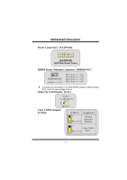
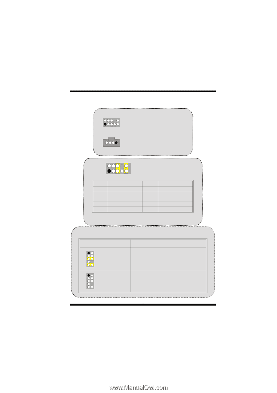
MMootthheerrbbooaarrdd DDeessccrriippttiioonn Audio Subsystem: JF_AUDIO/JCDIN1 2 JF_AUDIO1 1 (Front Audio Header) JCDIN1 1 (CD-ROM Audio-In Header) 22 1 10 9 JAUDIO1 Pin Assignment Pin Assignment 1 Mic In 2 Ground 3 Mic Power 4 Audio Power 5 RT Line Out 6 RT Line Out 7 Reserved 8 NC 9 LFT Line Out 10 LFT Line Out Pin 5 and 9 are routed to Front Panel Audio Out. Pin 6 and 10 are routed from Front Panel Audio Out. Front Panel Audio Connector/ Jumper Block Jumper Setting 12 3 5 7 4 6 Pin 5 and 6 Pin 9 and 10 9 10 1 3 5 246 No jumpers 7 9 10 installed Configuration Audio line out signals are routed to the back panel audio line out connector. Audio line out and mic in signals are available for front panel audio connectors. 10
-
 1
1 -
2
-
3
-
4
-
5
-
6
-
 7
7 -
 8
8 -
 9
9 -
 10
10 -
 11
11 -
 12
12 -
 13
13 -
 14
14 -
 15
15 -
 16
16 -
 17
17 -
18
-
19
-
20
-
21
-
22
-
23
-
24
-
25
-
26
-
27
 |
 |
M
M
M
o
o
t
t
t
h
h
h
e
e
r
r
b
b
o
o
o
a
a
a
r
r
r
d
d
D
D
D
e
e
e
s
s
s
c
c
r
r
i
i
p
p
p
t
t
i
i
i
o
o
o
n
n
n
10
Audio Subsystem: JF_AUDIO/JCDIN1
1
2
JF_AUDIO1
(Front
Audio Header)
1
JCDIN1
(CD-ROM Audio-In Header)
JAUDIO1
1
2
9
10
Pin
1
3
5
7
9
Pin
2
4
6
8
10
Mic In
Mic Power
RT Line Out
Reserved
LFT Line Out
Assignment
Ground
Audio Power
RT Line Out
NC
Assignment
LFT Line Out
Pin 5 and 9 are routed to Front Panel Audio Out.
Pin 6 and 10 are routed from Front Panel Audio Out.
1
2
Front Panel Audio Connector/ Jumper Block
9
10
Audio line out signals are routed
to the back panel audio line out connector.
Pin 5 and 6
Pin 9 and 10
Audio line out and mic in signals are
available for front panel audio connectors.
3
5
7
4
6
1
2
9
10
3
5
7
4
6
No jumpers
installed
Jumper Setting
Configuration