Biostar N4SIE-A7 N4SIE-A7 user's manual
Biostar N4SIE-A7 Manual
 |
View all Biostar N4SIE-A7 manuals
Add to My Manuals
Save this manual to your list of manuals |
Biostar N4SIE-A7 manual content summary:
- Biostar N4SIE-A7 | N4SIE-A7 user's manual - Page 1
N4SIE-A7 FCC Information and and, if not installed and used in accordance with the instructions, may cause harmful interference to radio communications. There is approval in writing. The content of this user's manual is subject to be changed without notice and we will not be responsible for - Biostar N4SIE-A7 | N4SIE-A7 user's manual - Page 2
System Memory 10 2.4 Connectors and Slots 11 Chapter 3: Headers & Jumpers Setup 13 3.1 How to Setup Jumpers 13 3.2 Detail Settings 13 Chapter 4: Useful Help 20 4.1 Award BIOS Beep Code 20 4.2 Extra Information 20 4.3 Troubleshooting 22 Chapter 5: NVIDIA SLI Function - Biostar N4SIE-A7 | N4SIE-A7 user's manual - Page 3
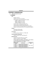
N4SIE-A7 CHAPTER 1: INTRODUCTION 1.1 MOTHERBOARD FEATURES A. Hardware CPU λ Supports LGA 775. λ Supports Intel Pentium 4 processor. λ Front Side Bus at the following frequency ranges: 533MT/s (133MHz Core Clock) 800MT/s (200MHz Core Clock) 1066MT/s (266MHz Core Clock) λ Supports Hyper- - Biostar N4SIE-A7 | N4SIE-A7 user's manual - Page 4
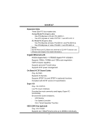
slots. PCI-EX1-1 and PCI-EX1-2. Notice: Normal Mode and SLI Mode are switched by SLI-NF4T selector card. (Please read Chapter 5 for detail information.) Gigabit Ethernet LAN λ NVIDIA Gigabit MAC + VITESSE Gigabit PHY VSC8201. λ Supports 10Mb/s, 100Mb/s and 1GB/s auto-negotiation. λ Half/Full duplex - Biostar N4SIE-A7 | N4SIE-A7 user's manual - Page 5
N4SIE-A7 Serial ATA II λ Controller integrated in NF4-SLI-MCP. λ Supports RAID functions. λ Supports Serial ATA 2.0 specification. λ Supports 4 Serial ATA (SATA) devices. λ Data transfer rate up to 1.5GB/s or 3GB/s. RAID Controller λ Controller integrated in NF4-SLI-MCP. λ NVIDIA RAID Technology: - - Biostar N4SIE-A7 | N4SIE-A7 user's manual - Page 6
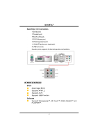
N4SIE-A7 Back Panel I/O Connectors λ 1 Serial port. λ 1 Parallel port. λ 1RJ-45 LAN jack. λ 1 PS/2 Mouse port. λ 1 PS/2 Keyboard port. λ 1 1394A Firewire port (optional). λ 4 USB 2.0 ports. λ 6 audio ports support 8 channels audio-out facilities. PS/2 Mouse PS/2 Keyboard Parallel Parallel Port - Biostar N4SIE-A7 | N4SIE-A7 user's manual - Page 7
N4SIE-A7 1.2 PACKAGE CHECKLIST λFDD Cable x 1 λHDD Cable x 1 λUser's Manual x 1 λSerial ATA Cable x 1 λBRI-2 SLI Bridge x 1 λFully Setup Driver CD x 1 λRear I/O Panel for ATX Case x 1 λSLI-NF4T Selector Card x 1 (pre-installed) λSPDIF Cable x 1 (optional) λUSB 2.0 Cable x 1 (optional) λRetention - Biostar N4SIE-A7 | N4SIE-A7 user's manual - Page 8
N4SIE-A7 1.3 LAYOUT AND COMPONENTS JKBMS1 JCOM1 JATXPWR2 LGA775 JCFAN1 CPU1 JPRNT1 Parallel Port COM1 DDR2_A1 DDR2_A2 DDR2_B1 DDR2_B2 FDD1 J1394_USB1 JUSBLAN1 JAUDIOF1 EARPHONEJACK1 Giga LAN JATXPWR1 JAUXPWR1 NF4-SLI-SPP PCI-Ex16-1 FAN1 Codec JCDIN1 Super I/O PCI-Ex1_1 PCI-Ex1_2 - Biostar N4SIE-A7 | N4SIE-A7 user's manual - Page 9
N4SIE-A7 CHAPTER 2: HARDWARE INSTALLATION 2.1 INSTALLING CENTRAL PROCESSING UNIT (CPU) CPU1 Special Notice: Remove Pin Cap before installation, and make good preservation for future use. When the CPU is removed, cover the Pin Cap on the empty socket to ensure pin legs won't be damaged. pin cap Step - Biostar N4SIE-A7 | N4SIE-A7 user's manual - Page 10
N4SIE-A7 Step 2: Look for the black cut edge on socket, and the white dot on CPU should point forwards this black cut edge. The CPU will fit only in the correct orientation. Step 2-1: Step 2-2: Step 3: Hold the CPU down firmly, and then close the lever to complete the installation. Step 4: Put the - Biostar N4SIE-A7 | N4SIE-A7 user's manual - Page 11
N4SIE-A7 2.2 FAN HEADERS These fan headers support cooling-fans built in the computer. The fan wiring and plug may be different according to the fan manufacturer. Connect the fan cable to the connector while matching the black wire to pin#1. JCFAN1: CPU Fan Power Header JCFAN1 4 1 Pin Assignment - Biostar N4SIE-A7 | N4SIE-A7 user's manual - Page 12
DDR2_A 1 DDR2_A 2 DDR2_B 1 DDR2_B 2 N4SIE-A7 2.3 INSTALLING SYSTEM MEMORY 1. Unlock a DIMM slot by pressing the retaining clips outward. Align a DIMM on the slot such that the notch on the DIMM matches the break on - Biostar N4SIE-A7 | N4SIE-A7 user's manual - Page 13
N4SIE-A7 2.4 CONNECTORS AND SLOTS FDD1: Floppy Disk Connector The motherboard provides a standard floppy disk connector that supports 360K, 720K, 1.2M, 1.44M and 2.88M floppy disk types. This connector supports the provided floppy drive ribbon cables. 34 33 2 1 IDE1/IDE2: Hard Disk Connector - Biostar N4SIE-A7 | N4SIE-A7 user's manual - Page 14
N4SIE-A7 PCI1~PCI3: Peripheral Component Interconnect Slots This motherboard is equipped with three standard 1.0a compliant. - Maximum bandwidth is up to 250MB/s per direction. PCI-EX16-1/PCI-EX16-2 (SLI Mode): - PCI Express 1.0a compliant. - Maximum bandwidth is up to 2GB/s per direction. PCI-EX16 - Biostar N4SIE-A7 | N4SIE-A7 user's manual - Page 15
N4SIE-A7 CHAPTER 3: HEADERS & JUMPERS SETUP 3.1 HOW TO SETUP JUMPERS The illustration shows how to set up jumpers. When the jumper cap is placed on pins, the - Biostar N4SIE-A7 | N4SIE-A7 user's manual - Page 16
N4SIE-A7 JATXPWR2: ATX Power Source Connector By connecting this connector, it will provide +12V to CPU power circuit. 2 1 3 4 Pin Assignment 1 +12V 2 +12V 3 Ground 4 Ground JAUXPWR1: PCI-Express x16 Slot Power Source Connector When SLI mode is enabled, please plug in this PEX power - Biostar N4SIE-A7 | N4SIE-A7 user's manual - Page 17
N4SIE-A7 JSPDIF_OUT/JSPDIF_IN1: Digital Audio-out Connectors (JSPDIF_IN1 is optional.) These connectors allow user to connect the PCI bracket SPDIF output or input header. JSPDIF_OUT: Pin - Biostar N4SIE-A7 | N4SIE-A7 user's manual - Page 18
N4SIE-A7 J1394PWR1 (optional): Power Source Header for 1394 Chip 3 1 Pin 1-2 Close: +3.3V for 1394 chipset (default). 3 1 Pin 2-3 Close: +3.3V SB for 1394 chipset. 3 1 J1394A1 (optional): Header - Biostar N4SIE-A7 | N4SIE-A7 user's manual - Page 19
N4SIE-A7 JUSB1~JUSB3: Headers for USB Ports at Front Panel This connector placing the jumper on pin2-3, it allows user to restore the BIOS safe setting and the CMOS data, please carefully follow the procedures to avoid damaging the motherboard. 13 Pin 1-2 close: Normal Operation (Default). 13 Pin - Biostar N4SIE-A7 | N4SIE-A7 user's manual - Page 20
N4SIE-A7 JCI1: Case Open Headers This connector allows system to monitor PC case open status. If the signal has been triggered, it will record to the CMOS and show the message on next boot-up. Pin Assignment 1 Case open signal 2 Ground 12 JSATA1~JSATA4: Serial ATA Connectors The motherboard has a - Biostar N4SIE-A7 | N4SIE-A7 user's manual - Page 21
N4SIE-A7 JPANEL1: Header for Front Panel Facilities This 24-pin connector includes Power-on, Reset, HDD LED, Power LED, Sleep button, speaker and IrDA Connection. It - Biostar N4SIE-A7 | N4SIE-A7 user's manual - Page 22
N4SIE-A7 CHAPTER 4: USEFUL HELP 4.1 AWARD BIOS BEEP CODE Beep Sound One long beep followed by two short beeps High-low siren sound One Short beep when system boot-up Long beeps every other second Meaning Video card not found or video card memory bad CPU overheated System will shut down - Biostar N4SIE-A7 | N4SIE-A7 user's manual - Page 23
N4SIE-A7 B. CPU Overheated If the system shutdown automatically after power on system for seconds, that means the CPU protection function has been activated. When the CPU is over heated, the motherboard will shutdown automatically to avoid a damage of the CPU, and the system may not power on again. - Biostar N4SIE-A7 | N4SIE-A7 user's manual - Page 24
N4SIE-A7 4.3 TROUBLESHOOTING Probable Solution 1. No power to the system at all 1. Make sure power cable is Power light don't illuminate, fan securely plugged in. inside power supply does not turn 2. Replace cable. on. 3. Contact technical support "CMOS Failure." Review system's equipment. - Biostar N4SIE-A7 | N4SIE-A7 user's manual - Page 25
N4SIE-A7 CHAPTER 5: NVIDIA SLI FUNCTION 5.1 REQUIREMENTS λOnly Windows XP supports SLI (Dual Video) function. λTwo identical SLI-ready graphics cards that are NVIDIA certified. λThe graphics card driver should support NVIDIA SLI technology. λThe power supply unit must provide at least the minimum - Biostar N4SIE-A7 | N4SIE-A7 user's manual - Page 26
N4SIE-A7 Step 3: Invert the selector card and insert the edge labeled "SLI MODE". Step 4: Push down the selector card until the retention clips snap into place. ○1 Insert the card with a degree about 450. ○2 Push the selector card - Biostar N4SIE-A7 | N4SIE-A7 user's manual - Page 27
N4SIE-A7 5.3 THINGS TO NOTICE λNormal Mode: - Only PEX16-1 slot supports PCI-Express x16 interface graphics card function. - PEX1-1 and PEX1-2 slots provide PCI-Express x1 interface expansion card function. λSLI Mode: - Use BRI-2 connector to link two SLI-ready PCI-E x16 interface graphics cards. - - Biostar N4SIE-A7 | N4SIE-A7 user's manual - Page 28
N4SIE-A7 Step 5: Connect a 4-pin ATX power cable to AUX power connector (JAUXPWR1), this will ensure the stabilization of your system. Notice: When under SLI mode, please make sure the power supply is at least 500W (and above). Step 6: Insert the SLI bracket supports the SLI Bridge (BRI-2) firmly. 26 - Biostar N4SIE-A7 | N4SIE-A7 user's manual - Page 29
N4SIE-A7 5.5 ENABLING MULTI-GPU FEATURE IN WINDOWS After the graphics cards are installed, enable the Multi-GPU feature in NVIDIA nView properties. Step 1: Click NVIDIA Settings icon on the Windows taskbar. Step 2: Select "nView Properties" in nView Desktop Manager pop-up menu. Step 3: Click " - Biostar N4SIE-A7 | N4SIE-A7 user's manual - Page 30
N4SIE-A7 Step 5: Select "NVIDIA GeForce" tab, and then click on "Multi-GPU" item on the left dialog box. Step 6: Check before "Enable SLI multi-GPU" item, and click on OK to complete the setting. 28 - Biostar N4SIE-A7 | N4SIE-A7 user's manual - Page 31
N4SIE-A7 CHAPTER 6: NVIDIA RAID FUNCTIONS 6.1 OPERATION SYSTEM λSupports Windows XP Home/Professional Edition, and Windows 2000 Professional. 6.2 RAID ARRAYS NVRAID supports the following types of RAID arrays: RAID 0: RAID 0 defines a disk striping scheme that improves disk read and writes times - Biostar N4SIE-A7 | N4SIE-A7 user's manual - Page 32
N4SIE-A7 RAID 1: Every read solutions, or as a form of automatic backup that eliminates tedious manual backups to more Block 1 Block 1 expensive and less reliable please refer to the Driver CD, or go to http://www.nvidia.com/page/pg_20011106217193.html to download NVIDIA nForce Tutorial Flash. - Biostar N4SIE-A7 | N4SIE-A7 user's manual - Page 33
N4SIE-A7 CHAPTER 7: WARPSPEEDER™ descriptions about BIOS model and chipsets. In addition, the frequency status of CPU, memory, AGP and PCI along with the CPU speed are original system speed or a suitable one. 7.2 SYSTEM REQUIREMENT OS Support: Windows 98 SE, Windows Me, Windows 2000, Windows XP - Biostar N4SIE-A7 | N4SIE-A7 user's manual - Page 34
N4SIE-A7 7.3 1. INSTALLATION Execute the setup execution file, and then the following dialog will pop up. Please click "Next" Finish" button. Usage: The following figures are just only for reference, the screen printed in this user manual will change according to your motherboard on hand. 32 - Biostar N4SIE-A7 | N4SIE-A7 user's manual - Page 35
N4SIE-A7 7.4 [WARPSPEEDER™] INCLUDES 1 TRAY ICON AND 5 PANELS 1. Tray Icon: Whenever the Tray Icon utility is launched, it will display a little tray icon on the right side - Biostar N4SIE-A7 | N4SIE-A7 user's manual - Page 36
N4SIE-A7 2. Main Panel If you click the tray icon, [WarpSpeeder™] utility will be invoked. Please refer to the following figure; the utility's first window you will see is Main Panel. Main Panel contains features as follows: a. Display the CPU Speed, CPU external clock, Memory clock, AGP clock, and - Biostar N4SIE-A7 | N4SIE-A7 user's manual - Page 37
N4SIE-A7 3. Voltage Panel Click the Voltage button in Main Panel, the button will be highlighted and the Voltage Panel will slide out to up as the following figure. In this panel, you can decide to increase CPU core voltage and Memory voltage or not. The default setting is "No". If you want to get - Biostar N4SIE-A7 | N4SIE-A7 user's manual - Page 38
N4SIE-A7 4. Overclock Panel Click the Overclock button in Main Panel, the button and "+3MHz button": provide user the ability to do real-time overclock adjustment. Warning: Manually overclock is potentially dangerous, especially when the overclocking percentage is over 110 %. We strongly recommend - Biostar N4SIE-A7 | N4SIE-A7 user's manual - Page 39
N4SIE-A7 c. "Auto-overclock button": User can click this button and [WarpSpeeder™] will set the best and stable performance and frequency automatically. [WarpSpeeder™] utility will execute a series of testing until system fail. Then system will do fail-safe reboot by using Watchdog function. After - Biostar N4SIE-A7 | N4SIE-A7 user's manual - Page 40
N4SIE-A7 6. About Panel Click the "about" button in Main Panel, the button will be highlighted and the About Panel will detail information in hints of all the chipset that are related to overclocking. You can also get the mainboard's BIOS model and the Version number of [WarpSpeeder™] utility. 38 - Biostar N4SIE-A7 | N4SIE-A7 user's manual - Page 41
N4SIE-A7 Note: Because the overclock, overvoltage, and hardware monitor features are controlled by several separate chipset, [WarpSpeeder™] divide these features to separate panels. If one chipset
-
 1
1 -
 2
2 -
 3
3 -
 4
4 -
 5
5 -
 6
6 -
 7
7 -
8
-
9
-
10
-
11
-
12
-
13
-
14
-
15
-
16
-
17
-
18
-
19
-
20
-
21
-
22
-
23
-
24
-
25
-
26
-
27
-
28
-
29
-
30
-
31
-
32
-
33
-
34
-
35
-
36
-
37
-
38
-
39
-
40
-
41
 |
 |

N4SIE-A7
i
FCC Information and Copyright
This equipment has been tested and found to comply with the limits of a Class
B digital device, pursuant to Part 15 of the FCC Rules. These limits are designed
to provide reasonable protection against harmful interference in a residential
installation. This equipment generates, uses and can radiate radio frequency
energy and, if not installed and used in accordance with the instructions, may
cause harmful interference to radio communications. There is no guarantee
that interference will not occur in a particular installation.
The vendor makes no representations or warranties with respect to the
contents here and specially disclaims any implied warranties of merchantability
or fitness for any purpose. Further the vendor reserves the right to revise this
publication and to make changes to the contents here without obligation to
notify any party beforehand.
Duplication of this publication, in part or in whole, is not allowed without first
obtaining the vendor’s approval in writing.
The content of this user’s manual is subject to be changed without notice and
we will not be responsible for any mistakes found in this user’s manual. All the
brand and product names are trademarks of their respective companies.