Biostar P4TSG PRO P4TSG Pro user's manual
Biostar P4TSG PRO Manual
 |
View all Biostar P4TSG PRO manuals
Add to My Manuals
Save this manual to your list of manuals |
Biostar P4TSG PRO manual content summary:
- Biostar P4TSG PRO | P4TSG Pro user's manual - Page 1
with the instructions, may part or in whole, is not allowed without first obtaining the vendor's approval in writing. The content of this user's manual is subject to be changed without notice and we will not be responsible for any mistakes found in this user's manual. All the brand and product - Biostar P4TSG PRO | P4TSG Pro user's manual - Page 2
CCoonntteenntt LAYOUT OF P4TSG PRO 1 COMPONENT INDEX 2 ENGLISH 3 P4TSG Pro Features 3 Package contents ...5 CPU Installation ...6 DDR DIMM Modules: DDRA1-2, DDRB1-2 7 Installing Wireless LAN Card 29 Introduction...29 System Requirement 29 Installation...30 Usage...31 TROUBLE SHOOTING 39 ii - Biostar P4TSG PRO | P4TSG Pro user's manual - Page 3
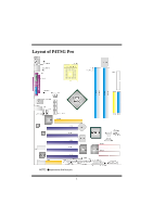
Layout of P4TSG Pro NOTE: ●represents the first pin. 1 - Biostar P4TSG PRO | P4TSG Pro user's manual - Page 4
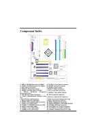
Component Index A. JKBV1: 5V/5VSB Selection for KB/MS Q. JPANEL1: Front Panel Connector B. JUSBV1: 5V/5VSB Selection for JUSB1 R. JSFAN1: System Fan Header C. Back Panel Connectors S. JGAME1: Game Header D. JAUDIO1: Front Audio Header T. RAID1-2: Raid Connectors E. JCDIN1: CD-ROM Audio-In - Biostar P4TSG PRO | P4TSG Pro user's manual - Page 5
English P4TSG Pro Features A. Hardware CPU Provides Socket-478. Supports the Intel Pentium 4 processor up to 3.06GHz. Front Side Bus at 400/533/800MHz. Supports Hyper-Threading. Supports Northwood and Prescott CPU. (Willamette not supported) Chipset North Bridge: Intel 865G. South Bridge: Intel - Biostar P4TSG PRO | P4TSG Pro user's manual - Page 6
low and eliminates usage barriers. Uses one RF card for Wireless LAN. LAN Chip: RTL8100B. Supports 10 Mb/s and 100 Mb/ auto-negotiation Half/Full duplex capability. Supports ACPI power management On Board AC'97 Sound Codec Chip: CMI9739A/ 9760. Compliant with AC'97 specification. AC97 2.2 interface - Biostar P4TSG PRO | P4TSG Pro user's manual - Page 7
APM1.2. Supports ACPI. Supports USB Function. Software Supports Warpspeeder™, 9th Touch™, FLASHER™, Watchdog™, StudioFun! ™. Offers the highest performance for Windows 98 SE, Windows 2000, Windows Me, Windows XP, SCO UNIX, linux, etc. Package contents HDD Cable X 2 FDD Cable X1 User's Manual X1 - Biostar P4TSG PRO | P4TSG Pro user's manual - Page 8
CPU Installation Step1: Pull the lever sideways away from the socket and then raise the lever up to a 90-degree angle. Step2: Look for the white dot/cut edge. The white dot/cut edge should point - Biostar P4TSG PRO | P4TSG Pro user's manual - Page 9
DDR DIMM Modules: DDRA1-2, DDRB1-2 Supports up to four DDR DIMMs(two DIMMs per channel), single-sided and/ or double-sided. For Dual Channel Operation, DIMMs must be populated in identical - Biostar P4TSG PRO | P4TSG Pro user's manual - Page 10
slot so that the wireless LAN card matches in the slot. Be sure to face the wireless LAN card with its components towards the inner part of the motherboard as it shows on the following picture. 8 - Biostar P4TSG PRO | P4TSG Pro user's manual - Page 11
2. Insert the wireless LAN card vertically and firmly into the slot so the wireless card is properly seated. 3. Screw the brackets. 4. Insert the wireless LAN antenna by turning it clockwise. Installing DDR Module 1. Unlock a DIMM slot by pressing the retaining clips outward. Align a DIMM on the - Biostar P4TSG PRO | P4TSG Pro user's manual - Page 12
cards. This PCI slot is designated as 32 bits. Accelerated Graphics Port Slot: AGP1 Your monitor will attach directly to that video card. This motherboard supports video cards for PCI slots, but it is also equipped with an Accelerated Graphics Port (AGP). An AGP card will take advantage of AGP - Biostar P4TSG PRO | P4TSG Pro user's manual - Page 13
Front Panel Connector: JPANEL1 JPANEL1 SLP PWR_LED ON/OFF 2 1 SPK HLED RST IR 24 23 IR Pin Assignment 1 +5V 3 NA 5 NA 7 Speaker 9 HDD LED (+) 11 HDD LED (-) 13 Ground 15 Reset Control 17 NA 19 NA 21 +5V 23 IRTX Function Speaker Connector Hard Drive LED Reset Button IrDA - Biostar P4TSG PRO | P4TSG Pro user's manual - Page 14
1 3 2 JATXPWR2 PIN Assignment PIN Assignment 1 +12V 3 Ground 2 +12V 4 Ground 5V / 5VSB Selection for KB: JKBV1 JKBV1 Assignment Description 1 5V for keyboard and mouse 3 Pin 1-2 close 1 3 Pin 2-3 close +5V +5V_SB 5V standby for keyboard and mouse to power on your system 5V/ - Biostar P4TSG PRO | P4TSG Pro user's manual - Page 15
Clear CMOS Jumper: JCMOS1 JCMOS1 Assignment 1 3 Pin 1-2 Close Normal Operation (default) 1 3 Pin 2-3 Close Clear CMOS Data ※ Clear CMOS Procedures: 1. Remove AC power line. 2. Set the jumper to "Pin 1-2 Close". 3. Wait for five seconds. 4. Set the jumper to "Pin 2-3 Close". 5. Power on the - Biostar P4TSG PRO | P4TSG Pro user's manual - Page 16
Game Header: JGAME1 15 1 16 2 JGAME1 Pin Assignment Pin 1 +5V 2 3 GPSB1 4 5 R_GPX2 6 7 MIDI-OUT 8 9 R_GPY2 10 11 GPSB2 12 13 MIDI-IN 14 15 NA 16 CD-ROM Audio-In Header: JCDIN1 Assignment +5V GPSB1 R_GPX1 Ground Ground R_GPY1 GPSA2 +5V Pin Assignment 1 Left - Biostar P4TSG PRO | P4TSG Pro user's manual - Page 17
Digital Audio Connector: JSPDIF_OUT1 Pin 1 1 2 JSPDIF_OUT1 3 Wake On LAN Header: JWOL1 Assignment +5V SPDIF_OUT Ground Pin Assignment 1 1 2 JWOL1 3 +5V_SB Ground Wake up Front USB Header: JUSB2/3 Pin Assignment Pin Assignment 9 11 +5V(fused) 2 +5V(fused) 10 23 USBP 4 USBP - Biostar P4TSG PRO | P4TSG Pro user's manual - Page 18
saved images as screensavers. You can also store the images on USB mass storage devices like flash disks and USB floppy disks. Hardware Requirements The supported hardware list of StudioFun! grows up every day. So please check the hwreq.txt located in the root of StudioFun! Installation CD to get - Biostar P4TSG PRO | P4TSG Pro user's manual - Page 19
based on the type of DVDs you will be playing. The installation procedure will then probe for the type of mouse installed. The distribution currently supports PS/2, USB and Serial mice. In case of serial mouse you will have to move the mouse when prompted. The other two are probed and - Biostar P4TSG PRO | P4TSG Pro user's manual - Page 20
Recovery In case of a MBR corruption, this option should be used. It will automatically probe the hard disk master boot record and find out the installed operating system(s). On success it will re-install the boot loader with correct options in the MBR. Any custom boot loader option specified from - Biostar P4TSG PRO | P4TSG Pro user's manual - Page 21
main shell of the StudioFun software. It basically comprises of two categories, one is the main "media control" part and the other is the "control panel". Media control The media control part of the Desktop has the following controls: 1. VCD This control will glow whenever a VCD is detected in a DVD - Biostar P4TSG PRO | P4TSG Pro user's manual - Page 22
will eject the default DVD/CD-ROM drive. 7. EXIT This is the "Power on/off" control of the Desktop (StudioFun! shell). Control Panel Control panel part has five icons, which are shortcuts to other applications present in the StudioFun software. Tool tips are provided on the icons when the mouse is - Biostar P4TSG PRO | P4TSG Pro user's manual - Page 23
1. Select Region Clicking this icon will invoke the application for selection DVD region settings. Refer to section 5.2 Select DVD Region application for more details. 2. Screensaver Clicking this icon will invoke the screensaver application. Refer to section 5.3 Screensaver for more details. 3. - Biostar P4TSG PRO | P4TSG Pro user's manual - Page 24
Playlists j. Image snapshot k. Audio resampling l. Software de-interlacing algorithms m. Configuration dialog n. Aspect ratio changing o. Fullscreen display • Supported File formats a. Video CD b. MPEG program streams (.mpg, .mpeg) c. ogg (.ogg) avi (.avi) d. asf (.asf, .wmv) e. QuickTime (.mov) 22 - Biostar P4TSG PRO | P4TSG Pro user's manual - Page 25
Video Codecs i. MPEG 1/2 j. MPEG 4 (aka OpenDivX) k. MS MPEG 4 a. Chapter 5: Software Details 10 l. Windows Media Video 7 m. Motion JPEG • Remote Control support. a. Infrared interface b. User-friendly • Usage of StudioFun! with CelomaChrome skin a. Select VCD button to play a VCD disc b. Select DVD - Biostar P4TSG PRO | P4TSG Pro user's manual - Page 26
l. j. Select hide button to hide the control panel of the player m. k. Select menu button to use menu's while playing DVD n. l. Select control button to adjust brightness / color o. Select setup button to modify the settings of the player p. Select f.scr button to show the video output of the player - Biostar P4TSG PRO | P4TSG Pro user's manual - Page 27
runs a graphics demo chosen at random. The demo is terminated as soon as there is any mouse or keyboard activity. The xscreensaver-demo program is the graphical user interface to xscreensaver. It lets you tune the various parameters used by the xscreensaver daemon, and browse through the graphics - Biostar P4TSG PRO | P4TSG Pro user's manual - Page 28
images is 5 seconds. Hyperball Hypercube Halo Strange • A snapshot of the application is shown below: Display Settings Display Settings Display setting is a program to change the current resolution settings of the Display. By default user of StudioFun will be given a choice to select between any of - Biostar P4TSG PRO | P4TSG Pro user's manual - Page 29
three resolutions. • 640x480 • 800x600 • 1024x768 The current resolution of the Display will be selected by default. It requires restart of the StudioFun to reflect the changes made. File Manager Overview File manger is an utility to copy files from deferent devices to hard disk and vice versa. User - Biostar P4TSG PRO | P4TSG Pro user's manual - Page 30
28 - Biostar P4TSG PRO | P4TSG Pro user's manual - Page 31
automatically rebooting the computer and then restart to a speed that is either the original system speed or a suitable one. System Requirement OS Support: Windows 98 SE, Windows Me, Windows 2000, Windows XP DirectX: DirectX 8.1 or above. (The Windows XP operating system includes DirectX 8.1. If you - Biostar P4TSG PRO | P4TSG Pro user's manual - Page 32
Installation 1. Execute the setup execution file, and then the following dialog will pop up. Please click "Next" button and follow the default procedure to install. 2. When you see the following dialog in setup procedure, it means setup is completed. If the "Launch the WarpSpeeder Tray Utility" - Biostar P4TSG PRO | P4TSG Pro user's manual - Page 33
Usage The following figures are just only for reference, the screen printed in this user manual will change according to your motherboard on hand. [WarpSpeeder™] includes 1 tray icon and 5 panels: 1. Tray Icon: Whenever the Tray Icon utility is launched, it will display a little tray icon on the - Biostar P4TSG PRO | P4TSG Pro user's manual - Page 34
This utility is responsible for conveniently invoking [WarpSpeeder™] Utility. You can use the mouse by clicking the left button in order to invoke [WarpSpeeder™] directly from the little tray icon or you can right-click the little tray icon to pop up a popup menu as following figure. The "Launch - Biostar P4TSG PRO | P4TSG Pro user's manual - Page 35
3. Voltage Panel Click the Voltage button in Main Panel, the button will be highlighted and the Voltage Panel will slide out to up as the following figure. In this panel, you can decide to increase CPU core voltage and Memory voltage or not. The default setting is "No". If you want to get the best - Biostar P4TSG PRO | P4TSG Pro user's manual - Page 36
4. Overclock Panel Click the Overclock button in Main Panel, the button will be highlighted and the Overclock Panel will slide out to left as the following figure. 34 - Biostar P4TSG PRO | P4TSG Pro user's manual - Page 37
3MHz button", "-1MHz button", "+1MHz button", and "+3MHz button": provide user the ability to do real-time overclock adjustment. Warning: Manually overclock is potentially dangerous, especially when the overclocking percentage is over 110 %. We strongly recommend you verify every speed you overclock - Biostar P4TSG PRO | P4TSG Pro user's manual - Page 38
hardware default setting or load the verified best and stable frequency according to the Recovery Dialog's setting. Note: Because the testing programs, invoked in Auto-overclock and Verify, include DirectDraw, Direct3D and DirectShow tests, the DirectX 8.1 or newer runtime library is required. And - Biostar P4TSG PRO | P4TSG Pro user's manual - Page 39
5. Hardware Monitor Panel Click the Hardware Monitor button in Main Panel, the button will be highlighted and the Hardware Monitor panel will slide out to left as the following figure. In this panel, you can get the real-time status information of your system. The information will be refreshed every - Biostar P4TSG PRO | P4TSG Pro user's manual - Page 40
hardware monitor features are controlled by several separate chipset, [ WarpSpeeder™ ] divide these features to separate panels. If one chipset is not on board, the correlative button in Main panel will be disabled, but will not interfere other panels' functions. This property can make [ WarpSpeeder - Biostar P4TSG PRO | P4TSG Pro user's manual - Page 41
Trouble Shooting PROBABLE SOLUTION No power to the system at all Power light don't * Make sure power cable is securely plugged in illuminate, fan inside power supply does not turn on. Indicator light on keyboard does not turn on * Replace cable * Contact technical support drive. board. Make - Biostar P4TSG PRO | P4TSG Pro user's manual - Page 42
05/5/2003 40
-
 1
1 -
 2
2 -
 3
3 -
 4
4 -
 5
5 -
 6
6 -
 7
7 -
8
-
9
-
10
-
11
-
12
-
13
-
14
-
15
-
16
-
17
-
18
-
19
-
20
-
21
-
22
-
23
-
24
-
25
-
26
-
27
-
28
-
29
-
30
-
31
-
32
-
33
-
34
-
35
-
36
-
37
-
38
-
39
-
40
-
41
-
42
 |
 |

P
P
4
4
T
T
S
S
G
G
P
P
r
r
o
o
i
FCC I
FCC I
FCC I
FCC Information
formation
formation
formation and Copyright
and Copyright
and Copyright
and Copyright
This equipment has been tested and found to comply with the limits of a
Class B digital device, pursuant to Part 15 of the FCC Rules. These limits
are designed to provide reasonable protection against harmful
interference in a residential installation. This equipment generates, uses
and can radiate radio frequency energy and, if not installed and used in
accordance with the instructions, may cause harmful interference to radio
communications. There is no guarantee that interference will not occur in
a particular installation.
The vendor makes no representations or warranties with respect to the
contents here of and specially disclaims any implied
warranties
of
merchantability or fitness for any purpose. Further the vendor reserves
the right to revise this publication and to make changes to the contents
here of without obligation to notify any party beforehand.
Duplication of this publication, in part or in whole, is not allowed without
first obtaining the vendor’s approval in writing.
The content of this user’s manual is subject to be changed without notice
and we will not be responsible for any mistakes found in this user’s
manual. All the brand and product names are trademarks of their
respective companies.