Biostar P4TSP-D2 P4TSP-D2 user's manual
Biostar P4TSP-D2 Manual
 |
View all Biostar P4TSP-D2 manuals
Add to My Manuals
Save this manual to your list of manuals |
Biostar P4TSP-D2 manual content summary:
- Biostar P4TSP-D2 | P4TSP-D2 user's manual - Page 1
energy and, if not installed and used in accordance with the instructions, may cause harmful interference to radio communications. There is no guarantee vendor's approval in writing. The content of this user's manual is subject to be changed without notice and we will not be responsible for any mistakes - Biostar P4TSP-D2 | P4TSP-D2 user's manual - Page 2
, Connectors & Slots 7 DEUTSCH 14 Die Spezifikationen von P4TSP-D2 14 Verpackungsinhalt 16 Einstellung der Jumper 16 Installation der CPU 16 DDR-DIMM-Modules: DDRA1/ DDRA2 17 Installation von Screensaver ...44 Display Settings...45 File Manager...46 TROUBLE SHOOTING 48 PROBLEMLÖSUNG 49 ii - Biostar P4TSP-D2 | P4TSP-D2 user's manual - Page 3
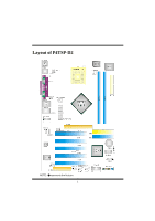
Layout of P4TSP-D2 NOTE: ●represents the first pin. 1 - Biostar P4TSP-D2 | P4TSP-D2 user's manual - Page 4
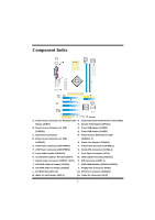
) X. IDE Connectors (IDE1-2) J. CD-ROM Audio-In Header (JCDIN2) Y. DDR DIMM Modules (DDRA1/ DDRA2) K. CD-ROM Audio-In Header (JCDIN1) Z. Floppy Disk Connector (FDD1) L. PCI BUS Slots (PCI 1-5) A1. CPU Fan Connector (JCFAN1) M. Wake On LAN Header (WOL1) B1. Audio DJ Connector (JDJ1) 2 - Biostar P4TSP-D2 | P4TSP-D2 user's manual - Page 5
P4TSP-D2 Features A. Hardware CPU Provides Socket 478. Supports the Intel Pentium 4 processor to 3.2GHz. Front Side Bus at 400/533/800MHz. Supports Hyper-Threading Technology. Supports Northwood CPU. (Willamette not supported) Chipset North Bridge: Intel 848P. South Bridge: Intel ICH5. Main Memory - Biostar P4TSP-D2 | P4TSP-D2 user's manual - Page 6
. 1 Audio DJ header. Dimensions ATX Form Factor: 20.3 X 30.5cm (W X L) B. BIOS & Software BIOS Award legal BIOS. APM1.2. ACPI. USB Function. Software Supports Warpspeeder™, 9th Touch™, BootBlockerTM, WinFlasherTM, FLASHER™ and StudioFun! ™ (optional). Offers the highest performance for Windows 98 SE - Biostar P4TSP-D2 | P4TSP-D2 user's manual - Page 7
StudioFun! Application CD X 1 (optional) USB 2.0 Cable X1 (optional) S/PDIF Cable X 1 (optional) Rear I/O Panel for when jumper cap is placed on these 2 pins. Jumper open Jumper close Pin 1-2 close CPU Installation Step1: Pull the lever sideways away from the socket and then raise the lever up - Biostar P4TSP-D2 | P4TSP-D2 user's manual - Page 8
CPU Fan Header: JCFAN1 3 Pin 1 1 2 JCFAN1 3 Assignment Ground +12V FAN RPM rate Sense Module 64MB/128MB/256MB/512MB/1GB *1 64MB/128MB/256MB/512MB/1GB *1 ***Only for reference*** Total Memory Size (MB) Max is 2GB Installing DDR Module 1. Unlock a DIMM slot by pressing the retaining clips - Biostar P4TSP-D2 | P4TSP-D2 user's manual - Page 9
motherboard supports video cards for PCI slots, but it is also equipped with an Accelerated Graphics Port (AGP). An AGP card will take advantage of AGP technology for improved video efficiency and performance, especially with 3D graphics. Communication Network Riser Slot: CNR1 The CNR specification - Biostar P4TSP-D2 | P4TSP-D2 user's manual - Page 10
Front Panel Connector: JPANEL1 SLP PWR_LED ON/OFF IR (+) (+) (-) 2 24 JPANEL1 1 23 (+) (-) SPK HLED RST IR Pin Assignment Function Pin Assignment 1 +5V Speaker 2 Sleep Control 3 NA Connector 4 Ground 5 NA 6 NA 7 Speaker 8 Power LED (+) 9 HDD LED (+) Hard Drive 10 - Biostar P4TSP-D2 | P4TSP-D2 user's manual - Page 11
5V standby voltage +5V Standby 1 Voltage Pin 2-3 close Note: In order to support this function "Power-on system via keyboard and mouse", "JKBV1" jumper cap JUSBV1: 5V for USB at the JUSB1 connector port +5V JUSBV2: 5V for USB at the JRJ45USB1 coonector port JUSBV3_4: 5V for USB at the JUSB2 - Biostar P4TSP-D2 | P4TSP-D2 user's manual - Page 12
Note: In order to support this function "Power-on system via USB device", "JUSBV1/JUSBV2/ JUSBV3_4" jumper cap should be placed on pin 2-3 individually. Clear CMOS Jumper: JCMOS1 JCMOS1 Assignment 3 Normal Operation (default) 1 Pin 1-2 Close 3 Clear CMOS - Biostar P4TSP-D2 | P4TSP-D2 user's manual - Page 13
AUDIO DJ Connector: JDJ1 1 5 Pin Assignment Pin 1 SMBDATA 2 JDJ1 3 INT_B 4 5 ATX_PWROK Game Header: JGAME1 A Coordinate Y 13 MIDI Input 14 Joystick A Button 2 15 NA 16 +5V CD-ROM Audio-In Header: JCDIN1/ JCDIN2 Pin 1 1 2 JCDIN1/ JCDIN2 3 4 Assignment Left Channel Input - Biostar P4TSP-D2 | P4TSP-D2 user's manual - Page 14
/ Rear Speaker Left 14 Left Line In/ Rear Speaker Left Digital Audio Connector: JSPDIF_OUT1 Pin 1 1 2 JSPDIF_OUT1 3 Assignment +5V SPDIF_OUT Ground 5V_SB Ground Wake up Front USB Header: JUSB2, JUSB3 Pin Assignment Pin 9 11 +5V(fused) 2 10 23 USB- 4 JUSB2/3 5 USB+ 6 7 Ground 8 - Biostar P4TSP-D2 | P4TSP-D2 user's manual - Page 15
Back Panel Connectors JKBMS1 PS/2 Mouse JUSB1 USB JPRNT1 Parallel Port JRJ45USB1 LAN (optional) Line In Speaker Out MIC In PS/2 Keyboard COM1 JCOM1 COM2 JCOM2 USB JAUDIO 6 Channel Speakers Speaker Out Line In/ Rear Speaker Mic In/ Center & Bass 13 - Biostar P4TSP-D2 | P4TSP-D2 user's manual - Page 16
Deutsch Die Spezifikationen von P4TSP-D2 A. Hardware CPU Uterstützung für Sockel 478. Unterstützung für den Intel Pentium® 4 Prozessor bis zu 3.2GHz. FSB mit 400/533/800MHz. Uterstützung für die Hyper-Threading Technologie. Unterstützung für Intel CPU Northwood. (Willamette wird nicht untergestützt) - Biostar P4TSP-D2 | P4TSP-D2 user's manual - Page 17
, PCI Power Management. Onboard AC'97 Sound Codec Chip: CMI9739A. Entspricht der Spezifikation Audio-Header. 1 S/PDIF-Header. 1 Audio-DJ-Header. Abmessung ATX Form-Factor: 20.3 X 30.5cm (W X L) B. BIOS & Software BIOS Award legal BIOS. Unterstützung für APM1.2. Unterstützung ACPI. Unterstützung USB - Biostar P4TSP-D2 | P4TSP-D2 user's manual - Page 18
X1 Treiber CD für Installation X1 StudioFun! Anwendung CD X 1 (optional) USB 2.0 Kable X1 (optional) S/PDIF Kable X 1 (optional) I/O-Rückwand für Pins. Jumper geschlossen Jumper geöffnet Pin1-2 geschlossen Installation der CPU Schritt 1: Ziehen Sie den Hebel seitlich vom Sockel weg. Heben - Biostar P4TSP-D2 | P4TSP-D2 user's manual - Page 19
Sie die Installation. Schritt 1 Schritt 2 Schritt 3 Schritt 4 CPU-Lüfter Header: JCFAN1 3 1 JCFAN1 Pin Beschreibung 1 Masse 2 +12V 3 Lüfter RPM Geschwindigkeit Sensor System-Lüfter Header: JSFAN1 1 3 Pin 1 JSFAN1 2 Beschreibung Masse +12V 3 Lüfter RPM Geschwindigkeit Sensor - Biostar P4TSP-D2 | P4TSP-D2 user's manual - Page 20
tzt die mitgelieferte Bandkabel des Diskettenlaufwerks. Festplattenanschlüsse: IDE1 und IDE2 Das Mainboard hat einen 32-Bit Enhanced PCI IDE-Controller, der die Modi PIO0~4, , welche nur Audio, Netzwerk und Modem unterstützt. Serial ATA Connector: JSATA1/JSATA2 Auf diesen Motherboard gibt es ein - Biostar P4TSP-D2 | P4TSP-D2 user's manual - Page 21
die der Spezifikation von SATA 1.0 entspricht ( Dtenübertragung mit 1.5Gb/S) Anschlüsse für die Vorderseite: JPANEL1 SLP PWR_LED ON/OFF IR (+) (+) (-) 2 24 JPANEL1 1 23 (+) (-) SPK HLED RST IR Pin Belegung Funktion Pin Belegung 1 +5V 2 Schlaf- Kontroll 3 Kein Lautsprecher- 4 - Biostar P4TSP-D2 | P4TSP-D2 user's manual - Page 22
System Anmerkung: Um die Funktion ─"Erwecken durch Tastatur/Maus" ─ zu aktivieren, müssen Pins 2-3 von JKBV1 durch die Jumperkappe verdeckt werden. Auswahl von Stromsmodi für USB: JUSBV1/ JUSBV2/ JUSBV3_4 JUSBV1/JUSBV2/ JUSBV3_4 Pin-Belegung Beschreibung 1 3 Pin 1-2 geschlossen JUSBV1: 5V - Biostar P4TSP-D2 | P4TSP-D2 user's manual - Page 23
: 5V reservierte Spannung für JRJ45USB1 zum Erwecken JUSBV3_4: 5V reservierte Spannung für JUSB2/3 zum Erwecken Anmerkung: Um die Funktion ─"Erwecken durch USB-Geräte"─zu aktivieren, müssen Pins 2-3 von "JUSBV1/JUSBV2/ JUSBV3_4"durch die Jumperkappe verdeckt werden. Jumper zum Löschen des CMOS - Biostar P4TSP-D2 | P4TSP-D2 user's manual - Page 24
9 Joystick B Koordierung Y 10 Masse 11 Joystick B Knopf 2 12 Joystick A Koordierung Y 13 MIDI Eingabe 14 Joystick A Knopf 2 15 Kein 16 +5V CD-ROM Audio-In Header: JCDIN1/ JCDIN2 Pin Belegung 1 Linkkanal Eingabe 1 2 Masse JCDIN1/ JCDIN2 3 Masse 4 Rechtkanal Eingabe 22 - Biostar P4TSP-D2 | P4TSP-D2 user's manual - Page 25
-Signal des rechten Kanals von der Vorderseite/ Lautsprecher-Signal des rechten Kanals von der Vorderseite 13 Audio-Signal des linken Kanals Audio-Signal des linken Kanals von von der Vorderseite/ Lautsprecher-Signal des linken 14 der Vorderseite/ Lautsprecher-Signal des linken Kanals von der - Biostar P4TSP-D2 | P4TSP-D2 user's manual - Page 26
1 2 3 WOL1 Masse Wake-up Front USB Header: JUSB2, JUSB3 Pin Belegung Pin 9 1 1 +5V(geschmelzt) 2 3 USB- 4 10 25 USB+ 6 JUSB2/3 7 Masse 8 9 Schlüsse 10 Belegung +5V(geschmelzt) USBUSB+ Masse Kein Anschlüsse für die Rückwand 24 - Biostar P4TSP-D2 | P4TSP-D2 user's manual - Page 27
6 Kanal Lautsprecher Lautsprecher Ausgang/ Fornt-Lautsprecher (L/R) Line-In/ Rücklautsprecher (L/R) Mikrofon Eingang/ Zentrallautsprecher & Bass WarpSpeederTM Introduction [ WarpSpeeder™ ], a new powerful control utility, features three user-friendly functions including Overclock Manager, - Biostar P4TSP-D2 | P4TSP-D2 user's manual - Page 28
descriptions about BIOS model and chipsets. In addition, the frequency status of CPU, memory, AGP and PCI along with the CPU speed are Support: Windows 98 SE, Windows Me, Windows 2000, Windows XP DirectX: DirectX 8.1 or above. (The Windows XP operating system includes DirectX 8.1. If you use Windows - Biostar P4TSP-D2 | P4TSP-D2 user's manual - Page 29
be automatically and immediately launched after you click "Finish" button. Usage The following figures are just only for reference, the screen printed in this user manual will change according to your motherboard on hand. 27 - Biostar P4TSP-D2 | P4TSP-D2 user's manual - Page 30
utility will be invoked. Please refer do the following figure; the utility's first window you will see is Main Panel. Main Panel contains features as follows: a. Display the CPU Speed, CPU external clock, Memory clock, AGP clock, and PCI clock information. b. Contains About, Voltage, Overclock, and - Biostar P4TSP-D2 | P4TSP-D2 user's manual - Page 31
will be highlighted and the Voltage Panel will slide out to up as the following figure. In this panel, you can decide to increase CPU core voltage and Memory voltage or not. The default setting is "No". If you want to get the best performance of overclocking, we recommend you click the - Biostar P4TSP-D2 | P4TSP-D2 user's manual - Page 32
30 - Biostar P4TSP-D2 | P4TSP-D2 user's manual - Page 33
3MHz button", "-1MHz button", "+1MHz button", and "+3MHz button": provide user the ability to do real-time overclock adjustment. Warning: Manually overclock is potentially dangerous, especially when the overclocking percentage is over 110 %. We strongly recommend you verify every speed you overclock - Biostar P4TSP-D2 | P4TSP-D2 user's manual - Page 34
c. "Auto-overclock button": User can click this button and [ WarpSpeeder™ ] will set the best and stable performance and frequency automatically. [ WarpSpeeder™ ] utility will execute a series of testing until system fail. Then system will do fail-safe reboot by using Watchdog function. After reboot - Biostar P4TSP-D2 | P4TSP-D2 user's manual - Page 35
panel, you can get model name and detail information in hints of all the chipset that are related to overclocking. You can also get the mainboard's BIOS model and the Version number of [ WarpSpeeder™ ] utility. 33 - Biostar P4TSP-D2 | P4TSP-D2 user's manual - Page 36
Note: Because the overclock, overvoltage, and hardware monitor features are controlled by several separate chipset, [ WarpSpeeder™ ] divide these 34 - Biostar P4TSP-D2 | P4TSP-D2 user's manual - Page 37
can take snapshots of video and customize the saved images as screensavers or photo slideshows. Of course, the images can be stored in USB mass storage devices like flash disks and USB floppy disks. Hardware Requirements The supported hardware list of StudioFun! updates regularly. So please check - Biostar P4TSP-D2 | P4TSP-D2 user's manual - Page 38
selecting "Cancel" will terminate the installation and reboot the machine. If Windows or GNU/Linux is the only OS installed on the hard disk with will then probe for the type of mouse installed. The distribution currently supports PS/2, USB and Serial mice. In case of serial mouse you will have to - Biostar P4TSP-D2 | P4TSP-D2 user's manual - Page 39
unsupported and undocumented hardware the above error message is popped. 4. No device found! This error message is given if there is no hard disk in the system. StudioFun! Recover Where there is a MBR (Master Boot record) corruption, the "StudioFun Recover" will automatically probe the hard disk - Biostar P4TSP-D2 | P4TSP-D2 user's manual - Page 40
a complete description of the Desktop application. Desktop This is the main shell of the StudioFun! software. It illustrates two main categories, one is the main "Media Control" part and the other is the "Control Panel". Media control The Media Control consists of the following functionalities: 1. - Biostar P4TSP-D2 | P4TSP-D2 user's manual - Page 41
put in to the drive when the Desktop (StudioFun! shell) is up and running, otherwise, the control will simply glow to inform the user about a AUDIO present in the DVD/CD-ROM drive. 5. FILE This control will glow whenever a File CD (CDs with other media type files) is detected in a DVD - Biostar P4TSP-D2 | P4TSP-D2 user's manual - Page 42
2. Screensaver Clicking this icon will invoke the screensaver application. Refer to section 5.3 Screensaver for more details. 3. Display Settings Clicking this icon will invoke the application for changing the screen resolutions. Refer to section 5.4, Display Settings for more details. 4. File - Biostar P4TSP-D2 | P4TSP-D2 user's manual - Page 43
volume, hue, saturation adjusting requires hardware/driver support) i. Playlist j. Image snapshot k. Audio re-sampling l. Software de-interlacing algorithms m. Configuration dialog n. Aspect ratio changing o. Full-screen display • Supported File Formats a. Video CD b. MPEG program streams (.mpg - Biostar P4TSP-D2 | P4TSP-D2 user's manual - Page 44
g. MPEG-Audio (.mp2, .mp3) h. WAV (.wav) Video CODEC i. MPEG 1/2 j. MPEG 4 (aka OpenDivX) k. MS MPEG 4 a. Chapter 5: Software Details 10 l. Windows Media Video 7 m. Motion JPEG • Remote Control Support. a. Infrared interface b. User-friendly • Usage of StudioFun! with CelomaChrome skin a. Select VCD - Biostar P4TSP-D2 | P4TSP-D2 user's manual - Page 45
settings of the player p. Select "f.scr" button to show the video output of the player in full screen mode q. Select "snap" button to take a snapshot of the currently playing video r. Select "plist" button to add / remove / manage playlist s. Select - Biostar P4TSP-D2 | P4TSP-D2 user's manual - Page 46
Screensaver Screensaver The xscreensaver daemon waits until the keyboard and mouse have been idle for a period, and then runs a graphics demo chosen at random. The demo is terminated as soon as there is any mouse or keyboard activity. The xscreensaver-demo program is the graphical user interface to - Biostar P4TSP-D2 | P4TSP-D2 user's manual - Page 47
various graphics demos randomly 2. Only one Screen Saver: When user chooses this option, screensaver displays only one graphics demo. 3. Blank Screen Only: When user chooses this option, screensaver only blanks the screen instead of displaying the graphics demo. 4. Disable Screen Saver: When user - Biostar P4TSP-D2 | P4TSP-D2 user's manual - Page 48
By default user of StudioFun! will be given a choice to select between any of the following three resolutions. • 640x480 • 800x600 • 1024x768 The current resolution of the Display will be selected by default. It requires restart of the StudioFun! to reflect the changes made. File Manager Overview - Biostar P4TSP-D2 | P4TSP-D2 user's manual - Page 49
47 - Biostar P4TSP-D2 | P4TSP-D2 user's manual - Page 50
Trouble Shooting PROBABLE SOLUTION No power to the system at all Power light don't * Make sure power cable is securely plugged in illuminate, fan inside power supply does not turn on. Indicator light on keyboard does not turn on * Replace cable * Contact technical support PROBABLE SOLUTION - Biostar P4TSP-D2 | P4TSP-D2 user's manual - Page 51
Problemlösung MÖGLICHE URSACHE LÖSUNG Das System hat keine Spannungsversorgung. * Versichern Sie sich, dass das Stromkabel richtig Die Stromanzeige leuchtet nicht, der Lüfter im angebracht ist Inneren der eingeschaltet. Stromversorgung Tastaturleuchten sind wird nicht nicht an. * Ersetzen - Biostar P4TSP-D2 | P4TSP-D2 user's manual - Page 52
08/4/2003 50
-
 1
1 -
 2
2 -
 3
3 -
 4
4 -
 5
5 -
 6
6 -
 7
7 -
8
-
9
-
10
-
11
-
12
-
13
-
14
-
15
-
16
-
17
-
18
-
19
-
20
-
21
-
22
-
23
-
24
-
25
-
26
-
27
-
28
-
29
-
30
-
31
-
32
-
33
-
34
-
35
-
36
-
37
-
38
-
39
-
40
-
41
-
42
-
43
-
44
-
45
-
46
-
47
-
48
-
49
-
50
-
51
-
52
 |
 |

P
P
4
4
T
T
S
S
P
P
-
-
D
D
2
2
i
FCC Information and Copyright
This equipment has been tested and found to comply with the limits of a
Class B digital device, pursuant to Part 15 of the FCC Rules. These limits
are designed to provide reasonable protection against harmful
interference in a residential installation. This equipment generates, uses
and can radiate radio frequency energy and, if not installed and used in
accordance with the instructions, may cause harmful interference to radio
communications. There is no guarantee that interference will not occur in
a particular installation.
The vendor makes no representations or warranties with respect to the
contents here of and specially disclaims any implied
warranties
of
merchantability or fitness for any purpose. Further the vendor reserves
the right to revise this publication and to make changes to the contents
here of without obligation to notify any party beforehand.
Duplication of this publication, in part or in whole, is not allowed without
first obtaining the vendor’s approval in writing.
The content of this user’s manual is subject to be changed without notice
and we will not be responsible for any mistakes found in this user’s
manual. All the brand and product names are trademarks of their
respective companies.