Bosch DVR1C1161 Installation Instructions - Page 8
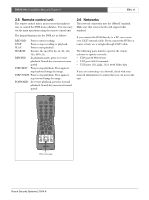
Power, 3.2 RS232 serial connector, 3.3 IR remote control eye connector, 3.4 LAN connector, 3.5
 |
UPC - 800549058353
View all Bosch DVR1C1161 manuals
Add to My Manuals
Save this manual to your list of manuals |
Page 8 highlights
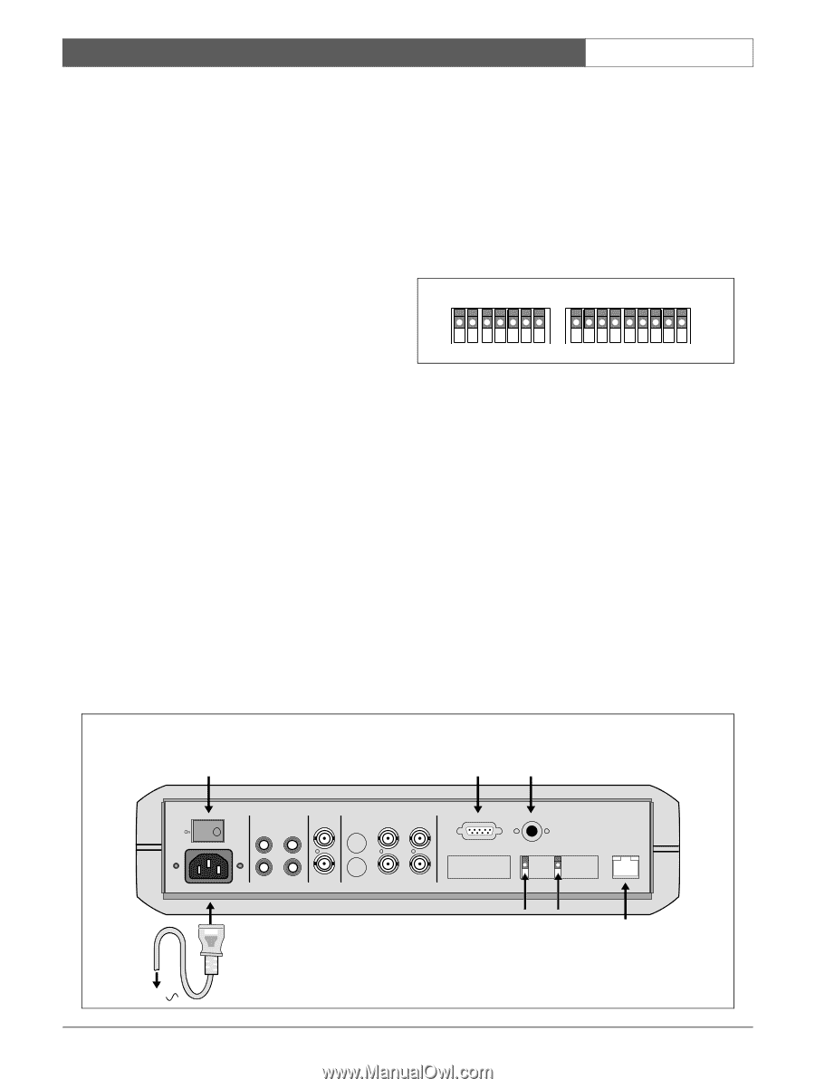
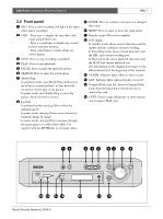
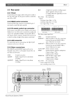
DVR1C1161 | Installation Manual | Chapter 2 EN | 8 2.3 Rear panel 2.3.1 Power Connect the power suppy cable to the power socket at the rear of the unit. Use the power switch to switch the unit ON or OFF. 2.3.2 RS232 serial connector Connect D-Sub 9-pin connector to the RS232 port if you want to control the unit remotely. REC: A high level external recording request signal* applied to this pin starts recording. When the signal drops to low, recording stops. NC1, NC2: No connections. * Signal - switching voltage High: > 2 Vdc - switching voltage Low: < 0.5 Vdc - max. input voltage: 12 Vdc GND ALM-IN ALM-RST REC NC1 NC2 GND GND ALM-NC ALM-NO ALM-CO VEXT DISKFULL NC3 NC4 GND 2.3.3 IR remote control eye connector If the remote control IR receiver window at the front is hidden from view (if the unit is mounted in a cupboard), connect the optionally available extension IR cable to the remote control connector. Position the receiver eye so that it is in line-of-sight of the remote control unit. 2.3.4 LAN connector To connect the unit to a network use the RJ-45 LAN connector at the rear of the unit. 2.3.5 Alarm connections The ALM-IN and ALM-RST inputs can be set to Normally Open (N.O.) or Normally Closed (N.C.) in the Alarm record menu. GND: ALM-IN: ALM-RST: Ground connection. Apply a signal* here to start alarm recording. Apply a signal* here to stop alarm recording. Alarm inputs The alarm output signals are: Alarm outputs GND: Ground connection. ALM-NC**: When an alarm occurs, the connection between this pin and ALM-COM is open. Otherwise it is closed. ALM-NO**: When an alarm occurs, the connection between this pin and ALM-COM is closed. Otherwise it is open. ALM-COM**: Alarm common contact. VEXT: Synchronization signal for multiplexer. Output voltage: 5 Vdc Output current: 100mA DISKFULL: Disk full alarm output signal. Output voltage: 5 Vdc Output current: 100mA NC3, NC4: No connections. * * contact voltage max: 24 Vdc max. switching current: 2A dc Power switch IR remote RS-232 control eye connector connector Power Off AC 100-240 Audio In1 In2 Mux main Monitor In S-Video In Video In Looping out Out1 Out2 Monitor Out Out Out 1 Out 2 GND ALM-IN ALM-RST REC NC1 NC2 GND GND ALM-NC ALM-NO ALM-CO VEXT DISKFULL NC3 NC4 GND RS 232 Remote Control LAN GND VEXT Alarm connector Network connector 100-240 Vac Bosch Security Systems | 2004-6
-
 1
1 -
2
-
 3
3 -
 4
4 -
 5
5 -
 6
6 -
 7
7 -
 8
8 -
 9
9 -
 10
10 -
 11
11 -
 12
12 -
 13
13 -
14
-
15
-
16
-
17
-
18
-
19
-
20
-
21
-
22
-
23
-
24
-
25
 |
 |