Bose 301 Series II Loud Owner's guide - Page 3
Selection, Connection, Phasing, Fusing
 |
View all Bose 301 Series II Loud manuals
Add to My Manuals
Save this manual to your list of manuals |
Page 3 highlights
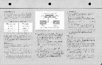
• • • 4. Wire Selection Audible sound coloration and/or power losscanoccur if the wire connecting the speakers to your amplifier or receiver is not thick enough. The table below specifies the minimum thickness of 2-conductor wire recommended for various speaker-to-amp distances. RECOMMENDED WIRE SIZES* Maximum Length Wire Gauge 30 feet ( 9 m) 18 (0.75 mm2) 45 feet (14 m) 16 (1.5 mm,) 70 feet (21 m) 14 (2.0 rnme) teseciatamovuerutregJertyleVeMedev.I.Onol =0508. Standard 2-conductor zipcord (available at electrical and hardware stores) can be used for speaker connection. This wireis often cobr-coded. or elsehas a ribbed line(s)running along one conductor for easy identification of the positive and negative leads. 5. Connection Follow the nexl procedure to assure that both 30110 speakers are property connected to your music system. Refer to FIGURE 2. a. Turn off your amplifier or receiver and unplug it from the ac power mains before connecting the loudspeakers. b. Separate the conductors at theend ofeach lengthof wire. Strip approximately Y2 inch (12 mm)ofinsulation off each conductor. c. Locate the push-type input terminals on the back of the left speaker cabinet. Note that there are Iwo terminals marked + (positive) and - (negative). STEREO AMPLIFIER OR RECEIVER Left Cutput ROIOutput Sn• Parts Loll Speaer Part 2 Right Srtaur 'Optional 1.5-ampere. Iasi-blow fuse (see Sectian 71 FIGURE 2. Speaker connection. d. Connect one wire conductor to the terminalmarked -on the left speaker. Connect the other end of the same conductor to the output terminal marked COM, GND. NEC or-en the left channel of your amplifier. Use thecolorcoding or ribbed hne(s) on the wire to be sure you are using the same conductor. e. In the same manner, connect the terminal on the left speaker to the output terminal marked POS or + on the left amplifier channel. (If your amplifier offers a choice of output impedances.use the terminalmarked 8 or 8 OHMS.) f. Repeat steps d and e above, connecting the right speaker to the rightoutput channel of your amplifier. g. Check very carefully to be certain that no loose strands of wire are accidentally "bridged" across the terminals GO either the speakers or the amplifier. Bridged wires create short circuits which can damage your amplifier. Repair any loose wire strands before operating you' amplifier or receiver. 6. Phasing Test If you are not certain that the speakers are connected to your amplifier "in phase" (i.e., positive to positive, negative to negative). perform this simple test: a. Set your sound system for MONO (monophonic) reproduction. Be sure the balance controlis centered or set to normal. b. Temporarily place the loudspeakers so that they are facing each other closely. c. Play music containing deep bass notes through the system. If the speakers are phased correctly, the sound will appear to come from a point between the speakers with full, natural bass response. d. If the music seems to be lacking in deep bass. reverse the and wire connections on one speaker and repeat the test. Use the connection that produces the most powerful bass. 7. Fusing Any loudspeaker can be damaged if the amplifier driving it should fail. Damagemay also occur by playing themusic so loudly that it sounds distorted. This can happen even with a low-poweredamplifieror receiver. Your 301speakers incorporateheavy-duty driver elements which are designed to resist many types of electrical stress. Fusing will provide additional protection. and is recommendedinmost applications. The fuseholders should be inserted into the + wire connecting eachspeaker toyour amplifier or receiver (seeFIGURE 2). Use1.5-ampere, fast-blow Buss AGC Series. Liftelfuse 3AG Series or equivalent fuses. A complete fuse kit including fuses and holders is available from the Bose Customer Service Department, The Mountain. Framingham, Massachusetts USA 01701 for $5.00. Ask for Me301Fuse Kit, Part Number108938-4.
-
 1
1 -
 2
2 -
 3
3 -
 4
4
 |
 |
