Bose 501 Series IV Loud Owner's guide - Page 2
tsose, Series, Direct/Reflecting, Loudspeaker, System
 |
View all Bose 501 Series IV Loud manuals
Add to My Manuals
Save this manual to your list of manuals |
Page 2 highlights
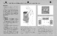
The•tsose' 501.': Series IV Direct/Reflecting • Loudspeaker System • Introduction Thank you for purchasing the Bose 501 Series IV Direct/ Reflecting!' Loudspeaker System. Its advanced design and quality construction will give youmany years of listening pleasure. Since you probably want to hear music from your 501 system as fast as possible. this guide is divided into tto parts. To properly unpack and connect your system, read Part 1. Alter you have connected your 501 system, and are enjoying some music, read Part 2. It explains how to double-check your connections. and gives you details on wire sizes. fusing, and room acoustics. To obtain the best possible performance, please read this entire guide thoroughly. PART 1 1. Unpacking Your 501 system is packaged in two separate cartons marked left speaker and right speaker. To unpack each carton, open its top, turn it upside down, and lift it off (see FIGURE 1). This will leave your speakers right side up. If either speaker appears to be damaged when unpacking, do not place the damaged unit into operation. Repack the speaker inits original carton. and notify your authorized Bose dealer immediately. 2. Connection 1. Turn off your amplifier or receiver, and unplug it from its outlet (ac power mains) before attempting to connect your speakers. 2. Slightly separate the conductors at the end of each length of speaker wire (use 18 gauge or larger wire). For more details, see Part 2. Section 4. Strip approximately 1/2 inch (12 mm) of insulation off each conductor. 3. Connect one wire conductor to the black terminal (marked "-") on the left speaker (see FIGURE 2). Connect the other end of the same conductor to the output terminal marked COM, GND. NEG, or "-"on the left channel of your receiver or amplifier (see FIGURE 3). FIGURE 1. Tounpack y.our swats (men the 100of the63iIC.IS. turn tile cartonsupSidedatin. and aide then', 01the Veakcia. 4. Similarly, connect the red terminal (marked " •i.") on the left speaker to the output terminal marked POS or " +" on the left channel of your amplifier or receiver. If your amplifier offers a choice of output impedances, use the terminal marked 8 or 8 OHMS. 5. Repeat Steps 3 and 4 above, connecting the right speaker to the right output channel of your amplifier or receiver. INPUT Jl FIGURE 2 ToMined the wifeS to WCSpartelS.(IOIXM the bellOnS beim...the connectors. and insel the ends of the Yam STEREO AMPLIFIER OR RECEIVER Leh Output ii • • i t gl: Right Output In !,i/ • • Left Speaker Right Speaker •Opiional 2-ampere last-blow (use (See Fusing) FIGURE 3. Make Sure to eurinCei. tannin& negative to neotnne as shonn to paSitheand 6. Check very carefully to be certain that no loose strands of wire are "bridged" from one terminal to the other on either of your speakers or on any of the amplifier outputs. Bridged wires create short circuits which can damage your amplifier or receiver. Repair any loose strands before plugging in your amplifier or receiver. 7. Plug in your amplifier or emeivef, turn it on, and enjoy!
-
 1
1 -
 2
2 -
 3
3 -
 4
4
 |
 |
