Bose 6.2 Owner's guide - Page 6
Bose 6.2 Manual
 |
View all Bose 6.2 manuals
Add to My Manuals
Save this manual to your list of manuals |
Page 6 highlights
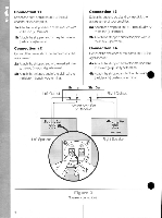
m Connection #1 le Selectonecordand connect it to theleft channel of your amplifier. la Attach one stripped end of the marked wire to the red ( +) terminal. b Attach the stripped end of the plain wire to the black (-) terminal. Connection #2 Connect the free ends of that same cord to the lett speaker. 2a Attach the stripped end of the marked wire to thered(+)push-type terminal. 2b Attach the stripped end of the plain wire to the black (-)push-type terminal. Left Output lb la Connection #3 Select the second cord and connect it to the right channel of your amplifier. 3a Attach one stripped end of the marked wire to the red(+)terminal. 3b Attach the stripped end of the plain wire to the black(-)terminal. Connection #4 Connect the free ends of that same cord to the nghtspeaker. 4a Attach the stripped end of the marked wire to the red (+) push-type terminal. 4b Attach the stripped end of the plain wire the black (-)push-type terminal. 3b 3a Right Output Stereo Amplifier or Receiver 2b a A 4b 4a Left Speaker 0 bLACK HU> Right Speake• INPUT • Figure 3 Speaker connections.
-
 1
1 -
 2
2 -
 3
3 -
 4
4 -
 5
5 -
 6
6 -
 7
7 -
 8
8 -
 9
9 -
 10
10 -
 11
11
 |
 |
