Bose 601Series II Loud Owner's guide - Page 3
Owner's, Manual
 |
View all Bose 601Series II Loud manuals
Add to My Manuals
Save this manual to your list of manuals |
Page 3 highlights
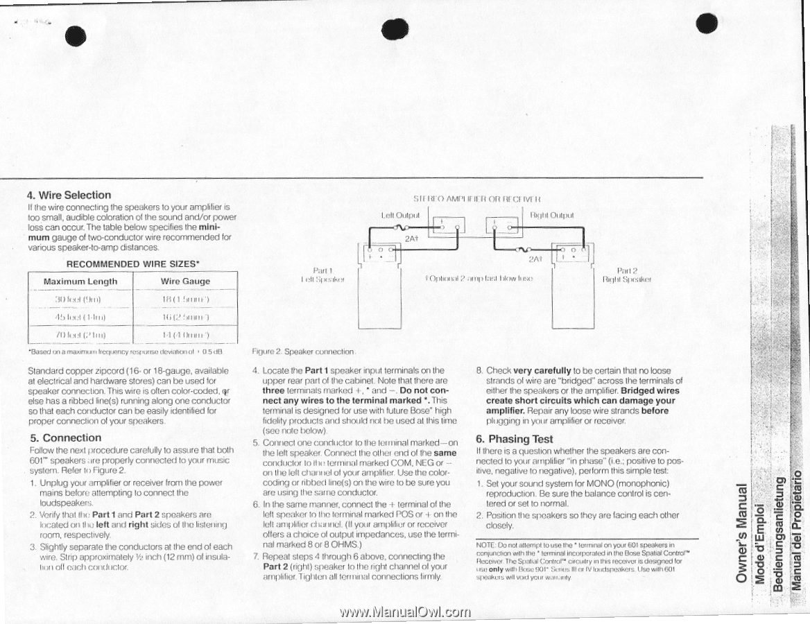
• 4. Wire Selection II the wire connecting the speakers to your amplifier is too small, audible coloration of the sound and/or power loss can occur. The table below specifies the minimum gauge o1 two-conductor wire recommended for various speaker4o-amp distances. RECOMMENDED WIRE SIZES' Maximum Length Wire Gauge 30feet 19m) !ohm') 45 luet ( 1-1110 16 (2!hunt /) lee! (2 Orem') 'Based on lumina/II 'fervency icspuuse devialion°I r 0 SOO Standard copper zipcord (16- or 18-gauge, available at electrical and hardware stores) can be used for speaker connection. This wire is often color-coded. re else has a ribbed bne(s) running along one conductor so that each conductor can be easily identified for proper connection of your speakers. 5. Connection Fodow the next trocecture carefully to assure that both 681- speakers are properly connectedIn your music system. Refer to Figure 2. 1. Unplug your amplifier or receiver from the power mains before attempting to connect the loudspeakers. 2. Verify that Ow Part1and Part 2 speakers are kwated on the left and right sides ol the listening room, respectively. 3. Slightly separate the conductors at the end of each wire. Strip approximately Y2 inch (12 mm) of insulaken oil each (XXII Pail 1 len SinNike. S11101) AMI'l IfIlft ()It litCI Wilt Oulgul 2A1 L' light Oulpul 0 2At 1(1inional amp lira I xvkas Pon ? I tight raker Figure 2. Speaker conneclion. 4. Locate the Part 1speaker input terminals on the upper rear part of the cabinet. Note that there are three terminals marked +. • and -. Do not connect any wires to the terminal marked'. This terminal is designed for use with future Bose' high fidelity products and should not be used al this time (see note below). 5. Conned one conductor to the lel 'lanai marked-on the left speaker. Connect the other end of the same conductor tollle terminal marked COM, MEG or -on the left channel ol your amplifier. Use the colorcoding or ribbed line(s) on the wire to be sure you are using the same conductor. 6. In the same manner, connect the + terminal of the felt speaker In the terminal marked POS or + on the felt an cl camel. (II your awhile( or receiver offers a choice of output impedances, use the termi- nal marked 8 or 8 OHMS.) 7. Repeal steps 4 through 6 above. connecting the Part 2 (right) speaker to the right channel ol your amplifier.1iglMen all terminal connections firmly. 8. Check very carefully to be certain that no loose strands of wire are "bridged" across the terminals of either the speakers or the amplifier. Bridged wires create short circuits which can damage your amplifier. Repair any loose wire strands before plugging in yolif amplifier or receiver. 6. Phasing Test II there is a question whether the speakers are connected lo your amplifier "in phase" (i.e.: positive to positive, negative to negative), perform this simple test: 1. Set your sound system for MONO (monophonic) reproduction. Be sure the balance control is cen• tered or set to normal. 2. Position the speakers so they are facing each ether closely. NOTE: Ou not Michell louse Inc • lounnal on your 601speakersin corgunolcn vulh the ' lemma' inCouxualed in the Bose SparkiContro- ritioeiyes The Spatial eCtilOr CIO y tnHis ICOLWIJI is dOSIOSOli to is o only Mk Bose OOP Solos lila, IV loudspeakets. Use wiii1601 eisxrll uml your ve;maiily Owner's Manual Mode d'Emploi C0 ' ta an "d 2 al Q. lA 717) C C Tu 0) 7 aj cu m 2
-
 1
1 -
 2
2 -
 3
3 -
 4
4
 |
 |