Bose Lifestyle 135 Home Entertainment Lifestyle® SA-2/SA-3 amplifier - Page 11
Bose Lifestyle 135 Home Entertainment Manual
 |
View all Bose Lifestyle 135 Home Entertainment manuals
Add to My Manuals
Save this manual to your list of manuals |
Page 11 highlights
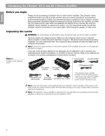
English Setting Up Your Lifestyle® Stereo Amplifier Mounting your Lifestyle® stereo amplifier Your Lifestyle® stereo amplifier can be placed on a shelf or mounted on a wall (Figure 3). • When placing the amplifier on a horizontal surface like a floor or shelf, the amplifier's rubber feet provide stability and prevent scratches. • ONLY when mounting the amplifier on a wall, remove the rubber feet and use the existing guide holes in the amplifier's enclosure for mounting hardware. See Figure 4 for recommended mounting methods and hardware. • When mounting the amplifier vertically or horizontally on a wall, ALWAYS mount the amplifier in an orientation shown in Figure 3. Figure 3 Installation options Connector panel on the left Connector panel up Figure 4 Mounting methods and hardware Shelf placement Vertically mounted on wall Horizontally mounted on wall Wood wall /3 32 in (2.25 mm) (4) #10 x 11/2 in (M5 x 36 mm) ¾ in (1.9 cm) minimum Wallboard 1/2 in (12 mm) (4) #10 x 21/2 in (M5 x 75 mm) (4) #10 (M5) 3/8 in (0.95 cm) minimum To mark mounting hole locations, remove the rubber feet, hold the amplifier in position, and mark the wall through the clearance holes in the housing. 9
-
 1
1 -
2
-
3
-
4
-
5
-
 6
6 -
 7
7 -
 8
8 -
 9
9 -
 10
10 -
 11
11 -
 12
12 -
 13
13 -
 14
14 -
 15
15 -
 16
16 -
17
-
18
-
19
-
20
-
21
-
22
-
23
-
24
-
25
-
26
-
27
-
28
-
29
-
30
-
31
-
32
 |
 |
