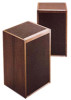
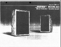
Bose Model 601 Owner's guide - Page 6
electrical
 |
View all Bose Model 601 manuals
Add to My Manuals
Save this manual to your list of manuals |
Page 6 highlights
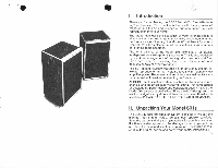
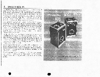
Installation Instructions B. CONNECTING THE SPEAKERS 1. Choosing The Correct Wire It is important to choose the correct wire size for your speaker system. If the wire used to connect the speakers to your amplifier is too small (has too much resistance), audible coloration of the sound and loss of power can result. The table below specifies the correct wire gauge necessary for various wire lengths. Copper zipcord, readily available at most electrical and hardware stores, can be used for speaker connection. Normally, this wire will have a ribbed line(s) running along one of the conductors so that each wire can be easily identified for proper phasing of your speaker system. RECOMMENDED CONNECTION WIREt Maximum Wire Length Wire Gauge 30 feet 18-gauge, zip-cord (or two-conductor wire) 45 feet 16-gauge, two-conductor wire 70 feet 14-gauge, two-conductor wire t The wire lengths shown in the table above were calculated on the basis of a maximum audible coloration of 1-.0.5d6. Following the guidelines provided. the most discerning listener will be unable to detect any coloration introduced by the speaker wire. Most listeners will not notice any effect even if wire lengths are increased by as much as 50%. 6 2. Wire Connection and Proper Phasing It is necessary to follow the next procedure carefully to assure that both speakers are properly connected and phased. (See Figure 3.) a. Strip approximately 1/2 inch of insulation from each end of the wires. Make sure that there are no loose wire strands. b. Place the "Part 1" speaker (identified by the rear label) on the left side of your room. Next. locate the "Pos" and "Corn" connection terminals on the rear of the speaker. c. Connect one conductor of the speaker wire to the terminal marked "Com" on the speaker. (The wire may be identified by a ribbed line(s) on the insulation or by the color of the wire.) Next connect the other end (of the same wire) to the terminal marked "com," "negative," or "minus," on the left channel of your amplifier. d. In the same manner, connect the"Pos" terminal on the left speaker to the terminal marked "Pos." "positive," or plus on the left channel of the amplifier.* e. Place the "Part 2" speaker on the right side of the room and repeat the connection procedure for the right amplifier channel. f. If there is a question whether the speakers are properly phased, a simple test can determine if your connections are correct. First, adjust your equipment for "mono" and play music containing deep bass through your speaker system. With the speakers pointed toward each other, the sound should come from a point near the center of the speakers with the music natural and full. (Be sure that the balance control on your amplifier is set in the center or "normal" position during this test.) *It your amplifier has a choice of impedances on the amplifier output, use the terminals marked "8" or B ohms.
-
 1
1 -
 2
2 -
 3
3 -
 4
4 -
 5
5 -
 6
6 -
 7
7 -
 8
8 -
 9
9 -
 10
10 -
 11
11 -
 12
12
 |
 |
