Boss Audio MR800 User Manual in English
Boss Audio MR800 Manual
 |
View all Boss Audio MR800 manuals
Add to My Manuals
Save this manual to your list of manuals |
Boss Audio MR800 manual content summary:
- Boss Audio MR800 | User Manual in English - Page 1
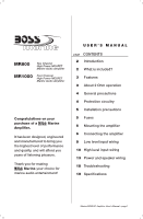
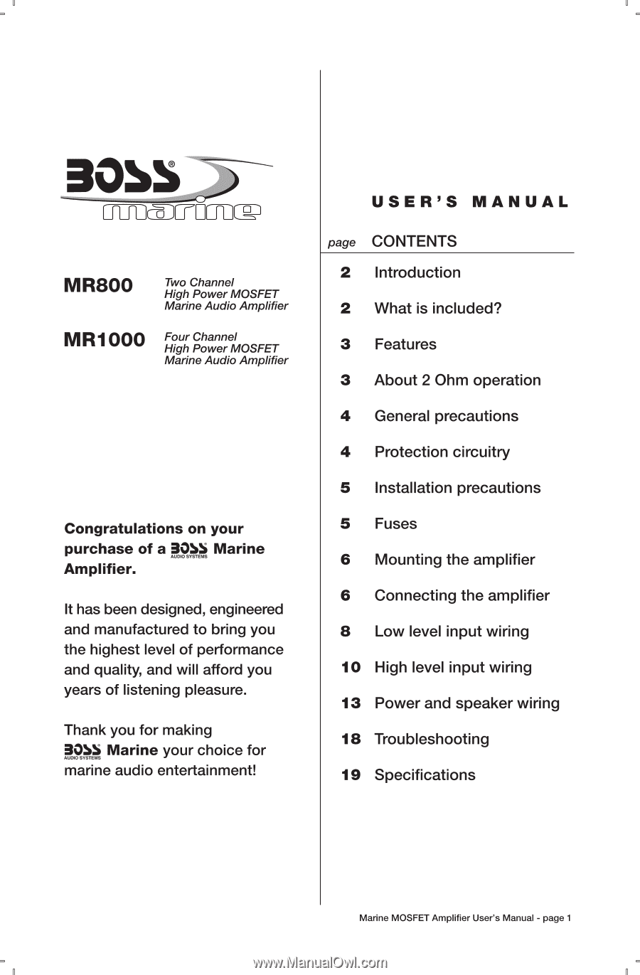
Two Channel High Power MOSFET Marine Audio Amplifier MR1000 Four Channel High Power MOSFET Marine Audio Amplifier Congratulations Low level input wiring 10 High level input wiring 13 Power and speaker wiring 18 Troubleshooting 19 Specifications Marine MOSFET Amplifier User's Manual - page - Boss Audio MR800 | User Manual in English - Page 2
the connections at the end of waterproof wires/cables, and tightly grommeted the wires as they pass through the end panels. included an input sensitivity control to help you integrate the amp into your system regardless of the nature of your input Marine MOSFET Amplifier User's Manual - page 2 - Boss Audio MR800 | User Manual in English - Page 3
Ohms. This means that you can install four 8 Ohm speakers per channel, when using parallel wiring. Increasing the number of woofers per channel at low frequencies (below 100Hz) produces an acoustic current, your music reproduction will be distorted. Marine MOSFET Amplifier User's Manual - page 3 - Boss Audio MR800 | User Manual in English - Page 4
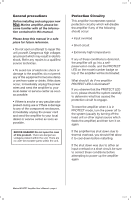
amplifier, please become familiar with all the information containedin this manual. Please keep this manualin a safe place for future drinks. If this does occur, immediately unplug the power wires and send the amplifier to your local dealer or service center as soon as possible. • If there is smoke - Boss Audio MR800 | User Manual in English - Page 5
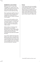
tank, fuel lines, hydraulic lines and electrical wiring. Never operate the amplifier when it is accident. Do not mount this amplifier so that wire connections are unprotected, in a pinched condition, in If you must replace a fuse in your Marine amp, use a fuse of exactly the same type and rating. - Boss Audio MR800 | User Manual in English - Page 6
to install it. Use a scribe or mounting screw, inserted through each of the amp's mounting holes, to mark the mounting surface. If the mounting surface is carpeted, . Connecting the amplifier Before doing any wiring, look through this manual and identify the diagrams to follow for power, input and - Boss Audio MR800 | User Manual in English - Page 7
all speakers, following the diagrams in this manual. Be sure to observe proper polarity to avoid audio phase problems. 7. Insert fuse(s) into input level to maximum unless your input level requires it. Ignoring these instructions will result in an input overload to the amplifier, and excessive - Boss Audio MR800 | User Manual in English - Page 8
Low Level Input Wiring Low-level (RCA) input wiring is preferred for best audio performance. Always use a high-quality RCA cable for best audio performance. NOTE:Do used in this installation 0 000000 To L/R Audio Outputs of head unit or signal processor Marine MOSFET Amplifier User's Manual - page 8 - Boss Audio MR800 | User Manual in English - Page 9
wiring is preferred for best audio performance. Always use a high-quality RCA cable for best audio performance. NOTE:Do not connectBOTH the high levelandlow levelinputs from your receiver to your amplifier at the same time! 4-Channel Amplifier with 4-ChannelAudioInputSource MR1000 's Manual - page 9 - Boss Audio MR800 | User Manual in English - Page 10
Wiring The high level input(s) should only be used when your head unit lacks RCA outputs. If the RCA outputs are not present, connect the speaker outputs from the receiver to the high level input connector of the amplifier. Be sure to observe polarity to avoid audio phase problems 's Manual - page 10 - Boss Audio MR800 | User Manual in English - Page 11
of the amplifier. Be sure to observe polarity to avoid audio phase problems. NOTE:Do not connectBOTH the high levelandlowlevelinputs from your receiver to your amplifier at the same time! 4-Channel Amplifier MR1000 with 4-ChannelAudioInput Source LOW LEVEL INPUTS not used in this installation - Boss Audio MR800 | User Manual in English - Page 12
of the amplifier. Be sure to observe polarity to avoid audio phase problems. NOTE:Do not connectBOTH the high levelandlowlevelinputs from your receiver to your amplifier at the same time! 4-Channel Amplifier MR1000 with 2-ChannelAudioInput Source LOW LEVEL INPUTS not used in this installation - Boss Audio MR800 | User Manual in English - Page 13
Power and Speaker Wiring 2 Channel and Bridged Modes 2-Channel Amplifier MR800 Two Channel Mode POWER CONNECTIONS SPEAKER OUTPUTS 0 0 BONS ....)marirow El CE to the L(+) amplifier lead. WHITE GREY/BLACK SPEAKER IMPEDANCE 4-8 OHMS SUBWOOFER Marine MOSFET Amplifier User's Manual - page 13 - Boss Audio MR800 | User Manual in English - Page 14
Power and Speaker Wiring 4 Channel Mode 4-Channel Amplifier MR1000 Four Channel Mode POWER CONNECTIONS SPEAKER OUTPUTS marine. El CE BLACK Chassis ground point to CH2 Speaker GREEN GREEN/ BLACK CH3 Speaker PURPLE PURPLE/ BLACK CH4 Speaker Marine MOSFET Amplifier User's Manual - page 14 - Boss Audio MR800 | User Manual in English - Page 15
Power and Speaker Wiring Bridged Mode Bridged Mode 4-Channel Amplifier MR1000 © POWER 0CONNECTIONS SPEAKER OUTPUTS A 30SS _).-FIrk-aw El CE BLACK = Chassis ground point L-- terminal. Connect the CH4 (-) lead to the Subwoofer 2 (-) terminal. Marine MOSFET Amplifier User's Manual - page 15 - Boss Audio MR800 | User Manual in English - Page 16
switch in the FULL position. Insert high pass filter capacitors and a low pass filter inductor into the wiring as shown below. Be sure to check the table at the bottom of this page to determine the filter inductor SUBWOOFER SPEAKER IMPEDANCE 8 OHMS Marine MOSFET Amplifier User's Manual - page 16 - Boss Audio MR800 | User Manual in English - Page 17
Speaker Wiring 4-Channel Amplifier MR1000 Tri-mode operation allows you to connect this amplifier to a pair of main speakers plus a subwoofer on PURPLE IMPEDANCE CH4 4 OHMS PURPLE/ BLACK Speaker SPEAKER IMPEDANCE 8 OHMS Low pass filter inductor Marine MOSFET Amplifier User's Manual - page 17 - Boss Audio MR800 | User Manual in English - Page 18
wiring diagram on the previous pages. If problems persist, read the following troubleshooting tips which may help eliminate the problems then the amplifier is faulty and needs servicing. Check that all fuses are OK. possible (without distortion) and the amp input level as low as Manual - page 18 - Boss Audio MR800 | User Manual in English - Page 19
: (7-ais" x 2.1/4" x ...) Two Channel Marine Amplifier MR800 125W x 2 Four Channel Marine Amplifier MR1000 100W x 4 400W x 2 250W x 4 800W x 1 500W x 2 2 Ohm Stereo/4 Ohm x 1 12-3/4" All specifications subject to change without notice. Marine MOSFET Amplifier User's Manual - page 19 - Boss Audio MR800 | User Manual in English - Page 20
Notes 3055 _c) cmc, icronc E4.]
-
 1
1 -
 2
2 -
 3
3 -
 4
4 -
 5
5 -
 6
6 -
 7
7 -
8
-
9
-
10
-
11
-
12
-
13
-
14
-
15
-
16
-
17
-
18
-
19
-
20
 |
 |
30b5
trait[
MR800
MR1000
Two
Channel
High
Power
MOSFET
Marine
Audio
Amplifier
Four
Channel
High
Power
MOSFET
Marine
Audio
Amplifier
Congratulations
on
your
purchase
of
a
39bl
Marine
Amplifier.
It
has
been
designed,
engineered
and
manufactured
to
bring
you
the
highest
level
of
performance
and
quality,
and
will
afford
you
years
of
listening
pleasure.
Thank
you
for
making
8.05
Marine
your
choice
for
marine
audio
entertainment!
USER'S MANUAL
page
CONTENTS
2
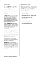
Introduction
2
What
is
included?
3
Features
3
About
2
Ohm
operation
4
General
precautions
4
Protection
circuitry
5
Installation
precautions
5
Fuses
6
Mounting
the
amplifier
6
Connecting
the
amplifier
8
Low
level
input
wiring
10
High
level
input
wiring
13
Power
and
speaker
wiring
18
Troubleshooting
19
Specifications
Marine
MOSFET
Amplifier
User's
Manual
-
page
1