Boss Audio MR800 User Manual in English - Page 15
Power, Speaker, Wiring, Channel, Bridged
 |
View all Boss Audio MR800 manuals
Add to My Manuals
Save this manual to your list of manuals |
Page 15 highlights
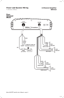
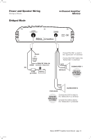
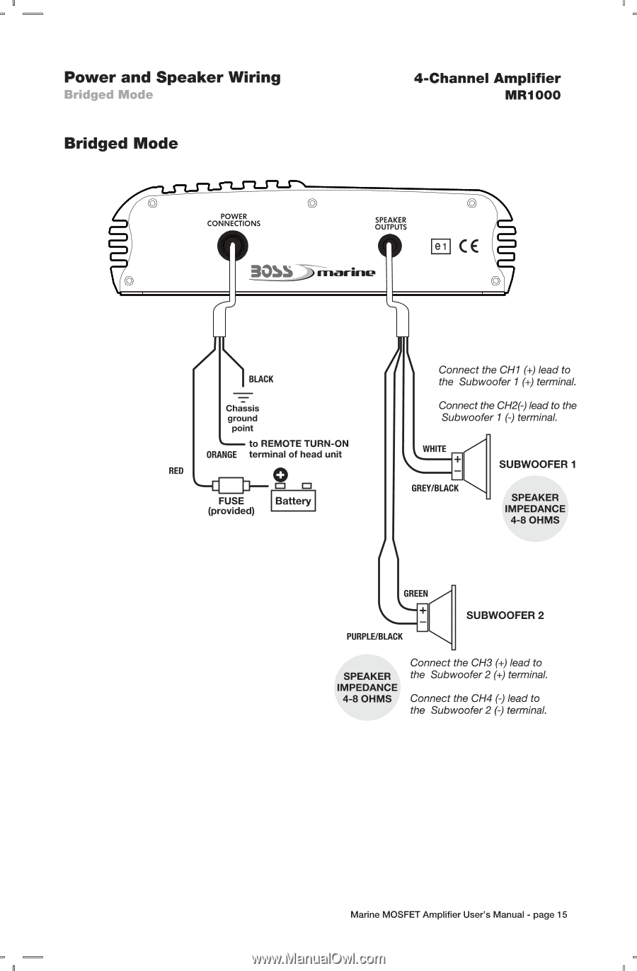
Power and Speaker Wiring Bridged Mode Bridged Mode 4-Channel Amplifier MR1000 © POWER 0CONNECTIONS SPEAKER OUTPUTS A 30SS _).-FIrk-aw El CE BLACK = Chassis ground point L-- to REMOTE TURN-ON ORANGE terminal of head unit RED L -El 0 rl- I=I I=I FUSE Battery (provided) A Connect the CH1 (+) lead to the Subwoofer 1(+) terminal. Connect the CH2(-) lead to the Subwoofer 1(-) terminal. =t _ GREY/BLACK I\ SUBWOOFER 1 SPEAKER IMPEDANCE 4-8 OHMS GREEN PURPLE/BLACK SUBWOOFER 2 SPEAKER IMPEDANCE 4-8 OHMS Connect the CH3 (+) lead to the Subwoofer 2 (-F) terminal. Connect the CH4 (-) lead to the Subwoofer 2 (-) terminal. Marine MOSFET Amplifier User's Manual - page 15
-
 1
1 -
2
-
3
-
4
-
5
-
6
-
7
-
8
-
9
-
 10
10 -
 11
11 -
 12
12 -
 13
13 -
 14
14 -
 15
15 -
 16
16 -
 17
17 -
 18
18 -
 19
19 -
 20
20
 |
 |
Power
and
Speaker
Wiring
4
-Channel
Amplifier
Bridged
Mode
MR1000
Bridged
Mode
©
POWER
CONNECTIONS
0
SPEAKER
OUTPUTS
A
30SS
_).-FIrk-aw
El
CE
RED
BLACK
=
Chassis
ground
point
L--
to
REMOTE
TURN
-ON
ORANGE
terminal
of
head
unit
0
L
—El
rl—
I=I
I=I
FUSE
(provided)
Battery
A
I\
PURPLE/BLACK
Connect
the
CH1
(+)
lead
to
the
Subwoofer
1
(+)
terminal.
Connect
the
CH2(-)
lead
to
the
Subwoofer
1
(-)
terminal.
=t
_
GREY/BLACK
GREEN
SUBWOOFER
1
SPEAKER
IMPEDANCE
4-8
OHMS
SUBWOOFER
2
Connect
the
CH3
(+)
lead
to
SPEAKER
the
Subwoofer
2
(-F)
terminal.
IMPEDANCE
4-8
OHMS
Connect
the
CH4
(-)
lead
to
the
Subwoofer
2
(-)
terminal.
Marine
MOSFET
Amplifier
User's
Manual
-
page
15