Brother International BAS-342G PS Instruction Manual - English - Page 22
INSTALLATION, <Power supply motor P.C. board>, <PMD P.C. board>, PMD P.C. board
 |
View all Brother International BAS-342G PS manuals
Add to My Manuals
Save this manual to your list of manuals |
Page 22 highlights
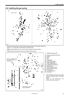
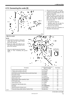
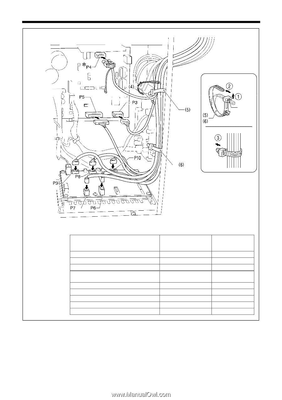
4. INSTALLATION Press the tab. 2568B Connector Machine head memory 7-pin Upper shaft motor 3-pin Synchronizer 14-pin Connector Work clamp pulse motor 4-pin black Thread trimmer solenoid 6-pin Tension release solenoid 4-pin Y pulse motor 4-pin blue X pulse motor 4-pin white NOTE: Route the X, Y and work clamp pulse motor harnesses so that they do not touch the PMD P.C. * Be sure to make the ground connection. (Refer to "4-14. Connecting the ground wire".) Connection location on power supply motor P.C. board P3 (HEAD-M) P4 (UVW) P5 (SYNC) Connection location on PMD P.C. board P3 (PPM) P6 (SOL1) P7 (SOL2) P8 (YPM) P10 (XPM) Cord clamp/cable tie (4) (5) (5), (6) Cable tie (5), (6) (5), (6) (5), (6) (5), (6) (5), (6) 13 BAS-342G PS
-
 1
1 -
2
-
3
-
4
-
5
-
6
-
7
-
8
-
9
-
10
-
11
-
12
-
13
-
14
-
15
-
16
-
 17
17 -
 18
18 -
 19
19 -
 20
20 -
 21
21 -
 22
22 -
 23
23 -
 24
24 -
 25
25 -
 26
26 -
 27
27 -
28
-
29
-
30
-
31
-
32
-
33
-
34
-
35
-
36
-
37
-
38
-
39
-
40
-
41
-
42
-
43
-
44
-
45
-
46
-
47
-
48
-
49
-
50
-
51
-
52
-
53
-
54
-
55
-
56
-
57
-
58
-
59
-
60
-
61
-
62
-
63
-
64
-
65
-
66
-
67
-
68
-
69
-
70
-
71
-
72
-
73
-
74
-
75
-
76
-
77
-
78
-
79
-
80
-
81
-
82
-
83
-
84
-
85
-
86
 |
 |
4. INSTALLATION
13
BAS-342G PS
<Power supply motor P.C. board>
<PMD P.C. board>
Connector
Connection location on
power supply motor P.C.
board
Cord clamp/cable tie
Machine head memory 7-pin
P3 (HEAD-M)
(4)
Upper shaft motor 3-pin
P4 (UVW)
(5)
Synchronizer 14-pin
P5 (SYNC)
(5), (6)
Connector
Connection location on
PMD P.C. board
Cable tie
Work clamp pulse motor 4-pin black
P3 (PPM)
(5), (6)
Thread trimmer solenoid 6-pin
P6 (SOL1)
(5), (6)
Tension release solenoid 4-pin
P7 (SOL2)
(5), (6)
Y pulse motor 4-pin blue
P8 (YPM)
(5), (6)
X pulse motor 4-pin white
P10 (XPM)
(5), (6)
<Removing>
Press
the tab.
<Securing>
2568B
NOTE:
Route the X, Y and work clamp pulse motor
harnesses so that they do not touch the
PMD P.C.
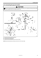
* Be sure to make the ground connection.
(Refer to "4-14. Connecting the ground
wire".)