Brother International BAS-342G Parts Manual - English - Page 5

Notes for using this parts book, CONTENTS

Page 5 highlights

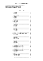
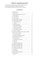
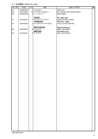
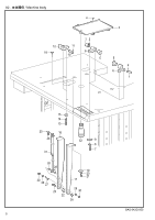
Notes for using this parts book 1. This book was prepared based on information available in May 2007. 2. Parts are subject to changes in design without prior notice. 3. Parts supplied as complete assemblies are circled by a dotted line. CONTENTS A1. Machine body 1 A2. Machine body 5 B. Upper shaft and needle bar mechanism 7 C1. Feed mechanism 9 C2. Feed mechanism 11 C3. Feed mechanism 13 D1. Work clamp lifter mechanism 15 D2. Work clamp lifter mechanism 17 E. Lower shaft mechanism 19 F. Lubrication 21 G. Threading mechanism 25 H. Bobbin winder mechanism 27 J. Thread trimmer mechanism 29 K. Thread wiper mechanism 33 L. Tension release mechanism 35 M1. Control box mechanism 37 M2. Control box mechanism (Power supply motor PCB) ....... 39 N. Power switch mechanism 41 P. Air pressure mechanism 43 Q. Power supply equipment mechanism 45 R. Operation panel mechanism 47 S. Motor mechanism 49 T. Foot switch pedal mechanism 51 U. Power table 53 V. Programmer 55 W1. Attachment set (Option parts 57 W2. Attachment set (Option parts 59 W3. Attachment set (Option parts 61 W4. Attachment set (Option parts 63 W5. Attachment set (Option parts 65 Z. Accessories 67 Wa. Warning labels 69 Ap. Parts list sorted by application 70 Ga. Gauge parts list 72 Index 73

  • 1
  • 2
  • 3
  • 4
  • 5
  • 6
  • 7
  • 8
  • 9
  • 10
  • 11
  • 12
  • 13
  • 14
  • 15
  • 16
  • 17
  • 18
  • 19
  • 20
  • 21
  • 22
  • 23
  • 24
  • 25
  • 26
  • 27
  • 28
  • 29
  • 30
  • 31
  • 32
  • 33
  • 34
  • 35
  • 36
  • 37
  • 38
  • 39
  • 40
  • 41
  • 42
  • 43
  • 44
  • 45
  • 46
  • 47
  • 48
  • 49
  • 50
  • 51
  • 52
  • 53
  • 54
  • 55
  • 56
  • 57
  • 58
  • 59
  • 60
  • 61
  • 62
  • 63
  • 64
  • 65
  • 66
  • 67
  • 68
  • 69
  • 70
  • 71
  • 72
  • 73
  • 74
  • 75
  • 76
  • 77
  • 78
  • 79
  • 80
  • 81
  • 82
  • 83
  • 84

1.
This book was prepared based on information available in May 2007.
2.
Parts are subject to changes in design without prior notice.
3.
Parts supplied as complete assemblies are circled by a dotted line.
A1.
Machine body
..................................................................
1
A2.
Machine body
..................................................................
5
B.
Upper shaft and needle bar mechanism
..........................
7
C1.
Feed mechanism
.............................................................
9
C2.
Feed mechanism
.............................................................
11
C3.
Feed mechanism
.............................................................
13
D1.
Work clamp lifter mechanism
...........................................
15
D2.
Work clamp lifter mechanism
...........................................
17
E.
Lower shaft mechanism
...................................................
19
F. Lubrication
.......................................................................
21
G.
Threading mechanism
.....................................................
25
H.
Bobbin winder mechanism
...............................................
27
J.
Thread trimmer mechanism
.............................................
29
K.
Thread wiper mechanism
................................................
33
L.
Tension release mechanism
............................................
35
M1.
Control box mechanism
...................................................
37
M2.
Control box mechanism (Power supply motor PCB)
.......
39
N.
Power switch mechanism
................................................
41
P.
Air pressure mechanism
..................................................
43
Q.
Power supply equipment mechanism
..............................
45
R.
Operation panel mechanism
............................................
47
S.
Motor mechanism
............................................................
49
T.
Foot switch pedal mechanism
.........................................
51
U.
Power table
......................................................................
53
V. Programmer
.....................................................................
55
W1.
Attachment set (Option parts)
..........................................
57
W2.
Attachment set (Option parts)
..........................................
59
W3.
Attachment set (Option parts)
..........................................
61
W4.
Attachment set (Option parts)
..........................................
63
W5.
Attachment set (Option parts)
..........................................
65
Z. Accessories
.....................................................................
67
Wa.
Warning labels
.................................................................
69
Ap.
Parts list sorted by application
.........................................
70
Ga.
Gauge parts list
................................................................
72
Index
................................................................................
73
CONTENTS
Notes for using this parts book