Brother International BAS-370E Instruction Manual - English - Page 11
Brother International BAS-370E Manual
 |
View all Brother International BAS-370E manuals
Add to My Manuals
Save this manual to your list of manuals |
Page 11 highlights
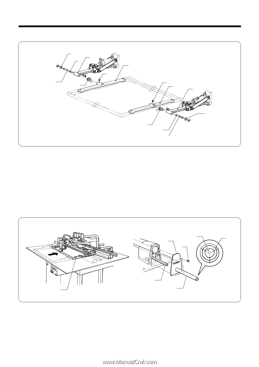
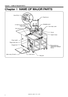
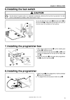
Chapter 3 INSTALLATION 4. Installing the work clamp hinge y u q w i t r i w q y e u t 1. Clamp hinge spring (R) e and hinge spring (L) r with the work clamp arm q and work clamp hinge w. 2. After placing the thrust washer y onto Y pulley shaft (A) t, insert Y pulley shaft (A) t into the work clamp arm q and work clamp hinge w. Note Insert Y pulley shaft (A) t into the hole of the work clamp hinge w so that the screw stop u is facing upward. 3. Secure the work clamp hinge w and Y pulley shaft (A) t with the set screw i. Note Make sure that the set screw i goes into the screw stop u of Y pulley shaft (A) t. 5. Installing the arm motor cover w t e r w q r 1. Move the feed mechanism q manually until it is as far into the machine as it will go. (The ball spline w should be extended fully toward the front when looking from behind the arm.) 2. Aligh the arm motor cover e with the rear of the arm so that there is even clearance between the tube section r and the ball spline w, and then secure with the accessory screws t. Note If noise is heard from the tubular section r of the arm motor cover e while the machine is operating, adjust the installation position of the arm motor cover e according to the procedure in step 2. above. BAS-364E, 366E, 370E, 375E 5
-
 1
1 -
2
-
3
-
4
-
5
-
 6
6 -
 7
7 -
 8
8 -
 9
9 -
 10
10 -
 11
11 -
 12
12 -
 13
13 -
 14
14 -
 15
15 -
 16
16 -
17
-
18
-
19
-
20
-
21
-
22
-
23
-
24
-
25
-
26
-
27
-
28
-
29
-
30
-
31
-
32
-
33
-
34
-
35
-
36
-
37
-
38
-
39
-
40
-
41
-
42
-
43
-
44
-
45
-
46
-
47
-
48
-
49
-
50
-
51
-
52
-
53
-
54
-
55
-
56
-
57
-
58
-
59
-
60
-
61
-
62
-
63
-
64
-
65
-
66
-
67
-
68
 |
 |