Brother International BAS-375E Parts Manual - English - Page 4
assemblies
 |
View all Brother International BAS-375E manuals
Add to My Manuals
Save this manual to your list of manuals |
Page 4 highlights
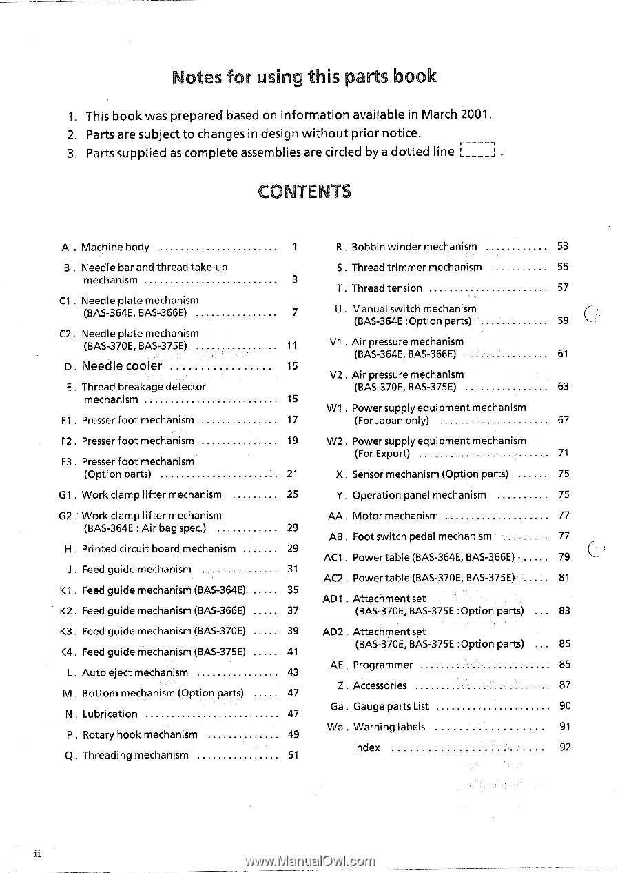
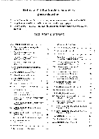
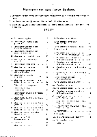
otes for usin this parts book 1. This book was prepared based on information available in March 2001. 2. Parts are subject to changes in design without prior notice. 3. Parts supplied as complete assemblies are circled by a dotted line . C TENTS A . Machine body B . Needle bar and thread take-up mechanism C1 . Needle plate mechanism (BAS-364E, BAS-366E) C2 . Needle plate mechanism (BAS-370E, BAS-375E) D. Needle cooler E . Thread breakage detector mechanism Fl . Presser foot mechanism F2 . Presser foot mechanism F3 . Presser foot mechanism (Option parts) G1 . Work clamp lifter mechanism G2 . Work clamp lifter mechanism (BAS-364E : Air bag spec.) H . Printed circuit board mechanism J . Feed guide mechanism K1 . Feed guide mechanism (BAS-364E) K2 . Feed guide mechanism (BAS-366E) K3 . Feed guide mechanism (BAS-370E) K4. Feed guide mechanism (BAS-375E) L . Auto eject mechanism M . Bottom mechanism (Option parts) N . Lubrication P . Rotary hook mechanism Q . Threading mechanism 1 R . Bobbin winder mechanism 53 S . Thread trimmer mechanism 55 3 T . Thread tension 57 7 U . Manual switch mechanism (BAS-364E :Option parts) 59 11 V1 . Air pressure mechanism (BAS-364E, BAS-366E) 61 15 V2 . Air pressure mechanism (BAS-370E, BAS-375E) 63 15 W1 . Power supply equipment mechanism 17 (For Japan only) 67 19 W2 . Power supply equipment mechanism (For Export) 71 21 X . Sensor mechanism (Option parts) 75 25 Y Operation panel mechanism 75 AA . Motor mechanism 77 29 AB . Foot switch pedal mechanism 77 29 AC1 . Power table (BAS-364E, BAS-366E) 79 31 AC2 . Power table (BAS-370E, BAS-375E) 81 35 AD1 . Attachment set 37 (BAS-370E, BAS-375E :Option parts) 83 39 AD2 . Attachment set 41 (BAS-370E, BAS-375E :Option parts) 85 43 AE . Programmer 85 47 Z . Accessories 87 47 Ga . Gauge parts List 90 49 Wa . Warning labels 91 51 Index 92 ii
-
 1
1 -
 2
2 -
 3
3 -
 4
4 -
 5
5 -
 6
6 -
 7
7 -
 8
8 -
 9
9 -
 10
10 -
11
-
12
-
13
-
14
-
15
-
16
-
17
-
18
-
19
-
20
-
21
-
22
-
23
-
24
-
25
-
26
-
27
-
28
-
29
-
30
-
31
-
32
-
33
-
34
-
35
-
36
-
37
-
38
-
39
-
40
-
41
-
42
-
43
-
44
-
45
-
46
-
47
-
48
-
49
-
50
-
51
-
52
-
53
-
54
-
55
-
56
-
57
-
58
-
59
-
60
-
61
-
62
-
63
-
64
-
65
-
66
-
67
-
68
-
69
-
70
-
71
-
72
-
73
-
74
-
75
-
76
-
77
-
78
-
79
-
80
-
81
-
82
-
83
-
84
-
85
-
86
-
87
-
88
-
89
-
90
-
91
-
92
-
93
-
94
-
95
-
96
-
97
-
98
-
99
-
100
-
101
-
102
-
103
-
104
-
105
-
106
-
107
-
108
-
109
-
110
 |
 |