Brother International BAS-416A Parts Manual - English - Page 4
Notes, using, parts, CONTENTS
 |
View all Brother International BAS-416A manuals
Add to My Manuals
Save this manual to your list of manuals |
Page 4 highlights
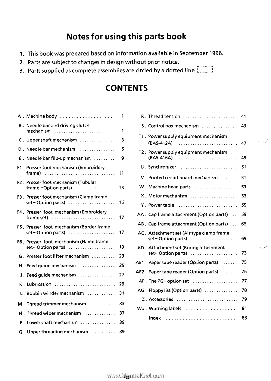
Notes for using this parts book 1. This book was prepared based on information available in September 1996. 2. Parts are subject to changes in design without prior notice. 3. Parts supplied as complete assemblies are circled by a dotted line L____] . CONTENTS A . Machine body 1 R . Thread tension 41 B . Needle bar and driving clutch mechanism C . Upper shaft mechanism D . Needle bar mechanism E . Needle bar flip-up mechanism S. Control box mechanism 43 1 T1 . Power supply equipment mechanism 3 (BAS-412A) 47 5 T2. Power supply equipment mechanism 9 (BAS-416A) 49 Fl . Presser foot mechanism (Embroidery U Synchronizer 51 frame) 11 V . Printed circuit board mechanism 51 F2 Presser foot mechanism (Tubular frame-Option parts) 13 W . Machine head parts 53 F3 . Presser foot mechanism (Clamp frame X. Motor mechanism 53 set-Option parts) 15 Y. Power table 55 F4. Presser foot mechanism (Embroidery frame set) 17 AA. Cap frame attachment (Option parts) 59 F5. Presser foot mechanism (Border frame AB. Cap frame attachment (Option parts) 65 set-Option parts) 17 AC. Attachment set (Air type clamp frame F6. Presser foot mechanism (Name frame set-Option parts) 69 set-"Option parts) 19 AD Attachment set (Boring attachment G . Presser foot lifter mechanism 23 set-Option parts) 73 H Feed guide mechanism 25 AE1 . Paper tape reader (Option parts) 75 . Feed guide mechanism 27 AE2 . Paper tape reader (Option parts) 76 K. Lubrication 29 AF . The PG1 option set 77 L. Bobbin winder mechanism 31 AG . Floppy list (Option parts) 78 Z. Accessories 79 M . Thread trimmer mechanism 33 Wa . Warning labels 81 N . Thread wiper mechanism 37 Index 83 P . Lower shaft mechanism 39 Q. Upper threading mechanism 39
-
 1
1 -
 2
2 -
 3
3 -
 4
4 -
 5
5 -
 6
6 -
 7
7 -
 8
8 -
 9
9 -
 10
10 -
11
-
12
-
13
-
14
-
15
-
16
-
17
-
18
-
19
-
20
-
21
-
22
-
23
-
24
-
25
-
26
-
27
-
28
-
29
-
30
-
31
-
32
-
33
-
34
-
35
-
36
-
37
-
38
-
39
-
40
-
41
-
42
-
43
-
44
-
45
-
46
-
47
-
48
-
49
-
50
-
51
-
52
-
53
-
54
-
55
-
56
-
57
-
58
-
59
-
60
-
61
-
62
-
63
-
64
-
65
-
66
-
67
-
68
-
69
-
70
-
71
-
72
-
73
-
74
-
75
-
76
-
77
-
78
-
79
-
80
-
81
-
82
-
83
-
84
-
85
-
86
-
87
-
88
-
89
-
90
-
91
-
92
-
93
-
94
-
95
-
96
-
97
-
98
-
99
-
100
 |
 |