Brother International HL 760 Service Manual
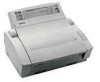
Brother International HL 760 - B/W Laser Printer Manual
 |
UPC - 012502562832
View all Brother International HL 760 manuals
Add to My Manuals
Save this manual to your list of manuals |
Brother International HL 760 manual content summary:
- Brother International HL 760 | Service Manual - Page 1
LASER PRINTER SERVICE MANUAL MODEL:HL-760 0O0 82 ELELTYL0M 00 - Brother International HL 760 | Service Manual - Page 2
part of this publication may be reproduced in any form or by any means without permission in writing from the publisher. Specifications are subject to change without notice. Trademarks: The brother logo is a registered trademark of Brother trademark and HP Laser Jet II, IIP Windows is - Brother International HL 760 | Service Manual - Page 3
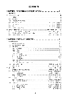
technical in maintaining the high printing quality and performance of the printer. This service manual covers HL-760. This manual consists of the following chapters: CHAPTER I FEATURES AND SPECIFICATIONS Features, specifications, etc. CHAPTER II THEORY OF OPERATION Basic operation of the - Brother International HL 760 | Service Manual - Page 4
Cover Sensor 2.3.2 Toner Empty Sensor 2.4 Drum Unit 2.4.1 2.4.2 2.4.3 2.4.4 Photosensitive Drum Primary Charger Developer Roller Transfer Roller I-1 1-1 1-3 1-3 1-3 . 1-4 Refer to HL-730 (P. 1-7) Refer to HL-730 (P.1-7) Refer to HL-730 (P.I-7) Refer to HL-730 (P. 1-8) Refer to HL-730 (P.I-10 - Brother International HL 760 | Service Manual - Page 5
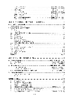
2.5.5 2.5.6 Charging Exposure stage Developing Transfer Drum Cleaning Stage Erasing Stage CHAPTER III DISASSEMBLY AND REASSEMBLY TROUBLESHOOTING 1. INTRODUCTION 1.1 Initial Check 1.2 Basic Procedure 2. IMAGE DEFECTS 2.1 Image Defect Examples 2.2 Troubleshooting Image Defects 3. TROUBLESHOOTING - Brother International HL 760 | Service Manual - Page 6
AND SPECIFICATIONS 1. FEATURES This printer has the following features: 1200 dpi Resolution and 6 ppm Printing Speed 1200 dots per inch (dpi) with microfine toner and six pages per minute (ppm) printing speed (A4 or Letter size paper). User-Friendly Operation for Windows The dedicated printer driver - Brother International HL 760 | Service Manual - Page 7
Printer Emulation Support This printer supports three printer emulation modes, HP LaserJet 5P, Epson FX-850, and IBM Proprinter XL. The printer also supports Management The printer provides its own data compression technology on its printer hardware and the supplied printer driver software, which can - Brother International HL 760 | Service Manual - Page 8
or letter -size paper at 5% print coverage) Drum unit, separated from toner cartridge IDT79R3041-20J 20MHz Automatic emulation selection among HP LaserJet 5P, EPSON FX-850, and IBM Proprinter XL Windows 95ANindows 3.1 driver, supporting Brother Native Compression mode and bi-directional capability - Brother International HL 760 | Service Manual - Page 9
2.3 Electrical and Mechanical Power source Power consumption Noise Temperature Humidity Dimensions (W x D x H) Weight U.S.A. and Canada: AC 110 to 120 V, 60Hz Europe and Australia: AC 220 to 240 V, 50Hz Printing: Standing by: Sleep: 480 W or less 60 W or less 10 W or less Printing: 50 dB A or - Brother International HL 760 | Service Manual - Page 10
diagram of this printer. External device e Laser scanner unit I II Drive block (Stepping motor) L. , / .... .. .,, Paper tray unit Paper tray e / Drum unit e N Transfer block • / Manual feed / / N Developing block i Drum C.Charging block } ( Cleaner block Toner cartridge - Brother International HL 760 | Service Manual - Page 11
(max.32 Mbytes) rill Option Serial I/O 4 (RS232C & RS422A) ASIC Oscillator (4MHz) Address Decoder DRAM Control Timer FIFO DATA EXTENSION CDCC Parallel I/O --4-0-- To PC Soft Support EEPROM (512 x8 bits) EEPROM I/O Motor Driver 11 To Panel Sensor PCB Fig. 2.2 Pr Engine Control I/O II - 2 - Brother International HL 760 | Service Manual - Page 12
1.3 Main PCB 1.3.1 CPU Core Fig. 2.3. shows the CPU circuit block on the main PCB. The CPU is a I DT 79R3041-20J which is driven with a clock frequency of 20 MHz. This clock frequency is made by dividing the source clock of 40.0 MHz into two. The address and data bus are 32 bits of ADO to AD31. The - Brother International HL 760 | Service Manual - Page 13
1.3.2 ASIC The ASIC is composed of Cell Based IC and has the following function blocks. (1) Oscillator circuit Generates the main clock for the CPU by dividing the source clock frequency into two. (2) Address Generator It forms address bass by ratchetting the AD bass with the ALE signal. (3) - Brother International HL 760 | Service Manual - Page 14
Data extension This circuit extents the compressed image data which are received from the PC,and writes the bit map data to the FIFO. (10) Software support Supports 16 x 16 rotation, bit expansion, bit search, and decimal point change. (11) EEPROM I/O One output port and one I/O port are assigned - Brother International HL 760 | Service Manual - Page 15
+5V° OV HCMPN R42 F102 R4 F102 k." 1,, Ova HCMPI .j DB I NTN p 40.00MHZ R13011 532 562 II STBN INITN SELIN HBUSY RESIST SW PSENS COVER TONER LOCK C41 C42 030 C43 103 I 49.08MHZ x C- I R37 000 I 3 L2 3 . 3uHA XINTN 0V0 II C45 102 ccceoi BDN XSENN XVDO VPPON +5V°-- I R47 472 - Brother International HL 760 | Service Manual - Page 16
1.3.3 ROM A program and font data are stored in the 4MBytes ROM. ROM is composed by the two 16 M bits masks and is mounted to the 42 pin IC socket. And 16 M bits Flash ROM Module can be mounted to it, too. CSROMOA I0RDN MAll MA12 MA13 MA14 MA15 NA16 MA17 NA19 NA19 MAll MA12 MA13 MA14 MA15 NA16 MA17 - Brother International HL 760 | Service Manual - Page 17
1.3.4 DRAM Two 4M-bit DRAMs (x 16bits) are used as the RAM. (03-06C) 0EN O( -024) BWEN OK -048) BCASN1 0* -04B) BCASNO (03-06C) I RASN MA00 MA01 MA02 MA03 MA04 MA05 MA06 MA07 MA08 #6 M5M44260AJ-8 1 VCC 6 20 VCC VCC VSS 21 VSS 35 40 VSS 7 COE 13 8 29 C17.1 CUCAS 2 4 CLCAS GRAS DQ 1 - Brother International HL 760 | Service Manual - Page 18
1.3.5 Optional RAM As the option RAM, 32 bit SIMM of 72 pin can be mounted. SIMM has one slot and can deal with 1 MBytes to 32 MBytes. MA[10 :003 SLOT 1 SIMM DOO /DO I /002 /003 /004 /DOS /D06 /007 /D08 /009 /D10 /011 /012 /1313 /D14 /015 /016 /017 /016 /019 /020 /021 /022 /023 /024 /025 /026 / - Brother International HL 760 | Service Manual - Page 19
1.3.6 Optional Serial I/O The interrupt of serial I/O are input to the EXINT terminal of the ASIC, and are recognized by the CPU. A 32-byte space for register is provided for this I/O, which are read and written to by the CPU. P4 OP I /F RESET OPCS c < 217 RD WR s - Brother International HL 760 | Service Manual - Page 20
1.3.8 Reset Circuit The reset IC is PST591DMT.The reset voltage is 4.2V (typ.) and the LOW period of reset is 50 ms (typ). RESETN CO3-02E) 0+5V +5 #12 PST591Dr1T VCC OUT GND MR ‹, R77 - Brother International HL 760 | Service Manual - Page 21
.9PB D2 RD3.9PB OE -01C) BDN O419) 2 74LS14 B (119) 4 < 3 74LS14 0A4 6 3 4 MODEL UMGSN +24VREP 01 pLDG2aYP_ I °1) I SW COVER RESIST PSENS TONER C. -06E) -0CE) C. -06E) (NE -0CE) LED I LED2 LED3 LED4 C. -05E) LOCK R15 21 R16 1 R13 711_. R14 A -100) FAN -07B) THERM 424VREP - Brother International HL 760 | Service Manual - Page 22
1.3.11 Paper Feed Motor Drive Circuit The motor driver is a TR array, The excitation method is 2-2 phase excitation with an bipolar drive. +5V 0V R30 183 R19 472 PMA PMAB PMB PMBB OVO +5V° - Brother International HL 760 | Service Manual - Page 23
problems by mishandling, be careful about the following precautions during maintenance work. (1) Always turn off the power switch before replacing parts power outlet. (2) Be careful not to lose screws, washers, or other parts removed. (3) Be sure to apply grease to the gears and applicable positions - Brother International HL 760 | Service Manual - Page 24
0 i @+ DRUM UNIT 0 TOP COVER MP PAPER TRAY ASSY FIXING UNIT C SCANNER UNIT BOTTOM r O MAIN4 PCB ASSY 0 0 BASE PLATE ASSY 0 ® PANEL SENSOR PCB ASSY @ • TRAY EXTENSION @ • PAPER - Brother International HL 760 | Service Manual - Page 25
(1) Open the top cover. (2) Lift out the drum unit. Top cover Drum unit Fig. 3.1 3.2 Top Cover (1) Open the top cover to the first lock position. (2) Prize up the top cover link and free it from the dowel - Brother International HL 760 | Service Manual - Page 26
(4) Open the top cover further, release the catch of the both side by sliding the top cover backward. Top cover t \ Bottom cover 1 1 ......./ , _____------ t ...... .. _________-- ---.--.----1 Catches Sub cover Fig. 3.3 3.3 Multi-purpose Paper Tray Assy (1) Tilt the left outward and pull - Brother International HL 760 | Service Manual - Page 27
(3) Disconnect the three connectors of the scanner unit from the panel sensor PCB. (4) Remove the screw and disassemble the Toner sensor PCB from the Scanner unit. Mirror Toner sensor PCB Scanner unit S Seal sponge 1 Connectors ( P2, P3, P9) ch11 Panel sensor PCB Fig. 3.6 NOTE: Never touch the - Brother International HL 760 | Service Manual - Page 28
Main PCB assy Hook , / I / F Shield assy Screws Fig. 3.7 Hook 3.7 Base Plate Assy NOTE: Prior to turning the printer upside-down, drum unit should be removed from the printer (1) Turn the printer upside down. (2) Remove the six M4 and eight M3 tapping screws. (3) Lift out the base plate assy - Brother International HL 760 | Service Manual - Page 29
3.8 Panel sensor PCB Assy (1) Remove the screw securing the panel sensor PCB assy. (Remove the part A from under the main shield) (2) Disconnect the seven connectors from the PCB (The three connectors have already disconnected at the disassembling scanner unit. See page, - Brother International HL 760 | Service Manual - Page 30
the screw securing the high-voltage power supply PCB assy. (2) Disconnect the four connectors from the PCB. Insulation sheet High-voltage power supply PCB assy Drum ground PCB harness (P4) GI Fan motor harness (P2) 7 Erase lamp harness (P3) /is Density volume HV Flat cable (P1) Density dial Fig - Brother International HL 760 | Service Manual - Page 31
3.12 Drive Unit (1) Remove the four screws securing the drive unit. Drive unit Fig. 3.13 3.13 Main Motor Assy and Motor Heat Sink (1) Remove the two screws securing the main motor assy. (2) Remove the two screws securing the motor heat sink. Motor heat sink 99 9 9 0 O Main motor assy - Brother International HL 760 | Service Manual - Page 32
3.14 Gears and Solenoid (1) Apply grease the point as shown below. Grease: MOLYKOTE EM-30LTKC-0 MOLYKOTE EM-D110 Apply grease those point after assembling. (EM-D110) Gear 20/94 Clutch release lever Clutch holder spring Solenoid ----7"--, Paper pick-up solenoid lever ik ' Gear 40/Inside cog - Brother International HL 760 | Service Manual - Page 33
TI No.97-P006 (1) Put the tray extension assy down toward the front of the printer, and pull the bottom of its both side legs outward to release it. Tray extension assy Multi-purpose paper tray assy Manual paper tray Fig. 3.16 3.16 Paper Eject Tray Assy (1) Open the paper eject tray - Brother International HL 760 | Service Manual - Page 34
the binder with tool like a scissors to remove the core secured to the body bottom. And then remove the motor harness, the solenoid and the drum ground PCB assy which are through the core. Core TFC Binder Drum ground PCB assy III Solenoid IN4l 1x Nk 4* Motor harness Fig. 3.19 III - 12 - Brother International HL 760 | Service Manual - Page 35
4. PACKING Documents -,;-----c-,c , Carton, SF assy R TN form A Insertion DC Dust cover Drum/Toner box assy Pad 4. Pad Bag Sheet kl Carton Fig. 3.20 III - 13 - Brother International HL 760 | Service Manual - Page 36
TROUBLESHOOTING 1. INSPECTION MODE 1.1 Incorporated Inspection Modes The printer incorporates the inspection modes such as the factory inspection mode and the test print mode. The inspection mode varies with the model of the printer DATA NV- RAM value dump mode DRUM+ALARM The ROM code update (only - Brother International HL 760 | Service Manual - Page 37
is installed.) DATA LED OFF OFF (No toner cartridge is installed.) DATA LED ON The procedure for the factory inspection mode is as follows. (1) Open the top cover and remove the drum unit. (2) Turn on the power of the printer while holding down the button. DRUM LED goes ON. (3) Lightly press the - Brother International HL 760 | Service Manual - Page 38
of a printer failure, error codes will be indicated as shown below. All the LEDs and the specific LEDs go ON by turns repeatedly. The specific combination of ONs indicates the type of the error. Type of error Fuser Malfunction Laser BD Malfunction Scanner Malfunction ROM Error D-RAM Error Service - Brother International HL 760 | Service Manual - Page 39
w SLOT1 SIMM LVPS POWER SWITCH CN1 CN101 MAIN PCB PANEL SENSOR PCB P8 ENGINE I/F P2 s MAIN MOTOR M P5 TONER SCANNER MOTOR AI P90 0 Plo P3 REGIST P4 DRUM GROUND PCB FAN LASER 41 SOLENOID I I T/R CLN GRID DEV P40 HVPS P2 P3 EJECT P1 P2 P7 P6 0 LEDs° 0 0 CSW V ERASE LAMP - Brother International HL 760 | Service Manual - Page 40
Appendix 2. Main PCB Circuit Diagram (113) 2 I 3 I 4 Q 1 I B 10 11 12 1R33) 680 A SYSCLK (03- 02E) d-SV OV 033-000) BUSDIR RESETS (03- 020 11'V :;% 9IDMT 1 VCC OUTS MR OV t-SV IDT79R3041-20d (0277 - Brother International HL 760 | Service Manual - Page 41
Appendix 3. Main PCB Circuit Diagram (213) 2 3 4 6 V 1 7 10 (03- 06C) WEN A CO3-050 XRASNEI (4171 74ALSI034 i. 2 04171 74ALS1034 R56 472 0( 048062 CA5N3 RSS 470 ORM% -Chi '? C4171 74ALS1034 2 2 Cit 171 74ALS1034 11 i2 9 (03- 06C) XRASN1 1417 1 74ALS1034 S 6 R54 470 . - Brother International HL 760 | Service Manual - Page 42
I 4 10 11 12 +SY 031 A +24,1 067316 A (0231103 IR24)103 hl NI J. .9 2 C* -0SF, VPPON [051 ($21 AN78012 OV 02 2501132 +24V .,EL UMCSN +24YREP -05. SW fm -05E) COVER CM -016) RESIST -GM PSENS . TONER -06E( LEDI CIE 06E> LED2 Cm NE) LED3 Cm OS. LOCK R 32 1 ,\A A/L-.3 - Brother International HL 760 | Service Manual - Page 43
Appendix 6. Low-Voltage Power Supply PCB Circuit Diagram 230V C) z L GFG BEA1 -n C5 • 11+ D14 NT C1 D13 D12 -- 7 e -, AA, R1 R5 ^AA, "--\ /2 O13 R8 • R13 R11 -0 R9 2J O CS) D4 "v^v^v-^v^v^s, • R2 R3 I IC22 R23 PC2 H N I I a C6 R20 R21 C11 D6 R17 C203 O • • J_ • - Brother International HL 760 | Service Manual - Page 44
Appendix 7. Low-Voltage Power Supply PCB Circuit Diagram 115V V GFG • BEA1 C8 • R5 • 0 • • \ C) C13 R8 • R13 R11 0 CS) -0 • R9 D4 v^v" -n C1 D
-
 1
1 -
 2
2 -
 3
3 -
 4
4 -
 5
5 -
 6
6 -
 7
7 -
8
-
9
-
10
-
11
-
12
-
13
-
14
-
15
-
16
-
17
-
18
-
19
-
20
-
21
-
22
-
23
-
24
-
25
-
26
-
27
-
28
-
29
-
30
-
31
-
32
-
33
-
34
-
35
-
36
-
37
-
38
-
39
-
40
-
41
-
42
-
43
-
44
 |
 |

LASER
PRINTER
SERVICE
MANUAL
MODEL:HL-760
0O0
82
ELELTYL0M
00