Brother International HL 760 Service Manual - Page 29
Panel, sensor, Shield, Solenoid, harness, cable, motor, voltage, power, supply, Heater, CN101
 |
UPC - 012502562832
View all Brother International HL 760 manuals
Add to My Manuals
Save this manual to your list of manuals |
Page 29 highlights
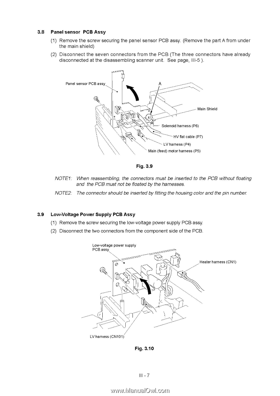
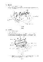
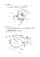
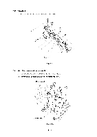
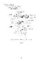
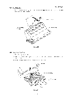
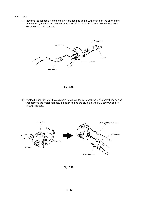
3.8 Panel sensor PCB Assy (1) Remove the screw securing the panel sensor PCB assy. (Remove the part A from under the main shield) (2) Disconnect the seven connectors from the PCB (The three connectors have already disconnected at the disassembling scanner unit. See page, III-5 ). Panel sensor PCB assy Main Shield r Solenoid harness (P6) HV flat cable (P7) LV harness (P4) Main (feed) motor harness (P5) Fig. 3.9 NOTE1: When reassembling, the connectors must be inserted to the PCB without floating and the PCB must not be floated by the harnesses. NOTE2: The connector should be inserted by fitting the housing color and the pin number 3.9 Low-Voltage Power Supply PCB Assy (1) Remove the screw securing the low-voltage power supply PCB assy. (2) Disconnect the two connectors from the component side of the PCB. Low-voltage power supply PCB assy ft, Heater harness (CN1) LV harness (CN101) Fig. 3.10 III - 7
-
 1
1 -
2
-
3
-
4
-
5
-
6
-
7
-
8
-
9
-
10
-
11
-
12
-
13
-
14
-
15
-
16
-
17
-
18
-
19
-
20
-
21
-
22
-
23
-
 24
24 -
 25
25 -
 26
26 -
 27
27 -
 28
28 -
 29
29 -
 30
30 -
 31
31 -
 32
32 -
 33
33 -
 34
34 -
35
-
36
-
37
-
38
-
39
-
40
-
41
-
42
-
43
-
44
 |
 |