Brother International KE-436C Parts Manual - English - Page 3
Notes, using, parts, CONTENTS
 |
View all Brother International KE-436C manuals
Add to My Manuals
Save this manual to your list of manuals |
Page 3 highlights
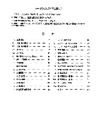
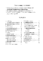
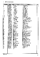
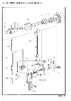
Notes for using this parts book 1 This book was prepared based on information available in Nobember 2002. 2 Parts are subject to changes in design without prior notice. 3 Parts supplied as complete assemblies are circled by a dotted line: 4 If the symbol * is found in the " Parts No: column, refer to the different parts lists, gauge parts list on page 60-68. CONTENTS A. Machine body 1 Bl. Upper shaft and needle bar mechanism 3 B2. Upper shaft and needle bar mechanism 5 C1. Feed mechanism 7 C2. Feed mechanism 11 C3. Feed mechanism (Option parts) 13 D. Work clamp lifter mechanism . 15 E. Lower shaft mechanism 17 F. Lubrication 21 G. Threading mechanism . 23 H. Bobbin winder mechanism ......... 25 J. Thread trimmer mechanism 27 K. Thread wiper mechanism 31 L. Thread take-up mechanism 31 M. Thread nipper mechanism . . 33 N. Synchronizer 35 P. Printed circuit board mechanism 35 Ql. Control box mechanism 37 Q2. Control box mechanism ......... 41 R. Air pressure mechanism . 45 S. Power supply equipment mechanism 47 T. Operation panel mechanism 49 U. Foot switch pedal mechanism (Option parts) 51 V. Power table 53 W. Programmer (Option parts) . 53 X. Attachment set (Option parts) 55 Z. Accessories • 57 Sp1. Diifferent Pads list 60 Sp2. Diifferent Parts list 61 Ga. Gauge parts list 62 Wa. Warning labels 63 Index 64
-
 1
1 -
 2
2 -
 3
3 -
 4
4 -
 5
5 -
 6
6 -
 7
7 -
 8
8 -
 9
9 -
10
-
11
-
12
-
13
-
14
-
15
-
16
-
17
-
18
-
19
-
20
-
21
-
22
-
23
-
24
-
25
-
26
-
27
-
28
-
29
-
30
-
31
-
32
-
33
-
34
-
35
-
36
-
37
-
38
-
39
-
40
-
41
-
42
-
43
-
44
-
45
-
46
-
47
-
48
-
49
-
50
-
51
-
52
-
53
-
54
-
55
-
56
-
57
-
58
-
59
-
60
-
61
-
62
-
63
-
64
-
65
-
66
-
67
-
68
-
69
-
70
-
71
-
72
 |
 |
