Brother International HE-800A Parts Manual - English - Page 3

Notes for using this parts book, CONTENTS - 21

Page 3 highlights

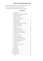
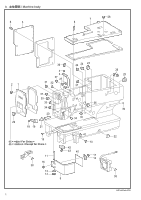
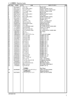
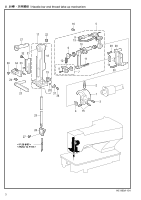
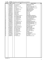
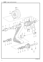
Notes for using this parts book 1. This book was prepared based on information available in November 2007. 2. Parts are subject to changes in design without prior notice. 3. Parts supplied as complete assemblies are circled by a dotted line. CONTENTS A. Machine body 1 B. Needle bar and thread take-up mechanism ...... 3 C. Upper shaft mechanism 5 D. Zigzag mechanism 7 E. Emergency stop mechanism 9 F. Presser foot mechanism 11 G. Feed mechanism 13 H. Cutter mechanism 17 J. Thread breakage detector mechanism 19 K. Rotary hook mechanism 21 L. Lower shaft mechanism 23 M. Lubrication 25 N. Threading mechanism 29 P. Bobbin winder mechanism 33 Q. Upper thread trimmer mechanism 35 R. Lower thread trimmer mechanism 37 S. Synchronizer 41 T1. Control box mechanism 43 T2. Control box mechanism 45 T3. Control box (PCB) mechanism 47 U. Power supply equipment mechanism 49 V. Operation panel mechanism 51 W. Motor mechanism 53 X. Safety cover 55 Y. Attachment set (Option parts 57 Z1. Accessories 59 Z2. Accessories 61 Z3. Accessories 63 Ga1. Gauge parts list 65 Ga2. Gauge parts list 66 Ga3. Gauge parts list 67 Wa. Warning labels 68 Index 69

  • 1
  • 2
  • 3
  • 4
  • 5
  • 6
  • 7
  • 8
  • 9
  • 10
  • 11
  • 12
  • 13
  • 14
  • 15
  • 16
  • 17
  • 18
  • 19
  • 20
  • 21
  • 22
  • 23
  • 24
  • 25
  • 26
  • 27
  • 28
  • 29
  • 30
  • 31
  • 32
  • 33
  • 34
  • 35
  • 36
  • 37
  • 38
  • 39
  • 40
  • 41
  • 42
  • 43
  • 44
  • 45
  • 46
  • 47
  • 48
  • 49
  • 50
  • 51
  • 52
  • 53
  • 54
  • 55
  • 56
  • 57
  • 58
  • 59
  • 60
  • 61
  • 62
  • 63
  • 64
  • 65
  • 66
  • 67
  • 68
  • 69
  • 70
  • 71
  • 72
  • 73
  • 74
  • 75
  • 76
  • 77
  • 78
  • 79
  • 80

1.
This book was prepared based on information available in November 2007.
2.
Parts are subject to changes in design without prior notice.
3.
Parts supplied as complete assemblies are circled by a dotted line.
A.
Machine body
....................................................
1
B.
Needle bar and thread take-up mechanism
......
3
C.
Upper shaft mechanism
....................................
5
D.
Zigzag mechanism
............................................
7
E.
Emergency stop mechanism
.............................
9
F.
Presser foot mechanism
....................................
11
G.
Feed mechanism
...............................................
13
H.
Cutter mechanism
.............................................
17
J.
Thread breakage detector mechanism
..............
19
K.
Rotary hook mechanism
....................................
21
L.
Lower shaft mechanism
....................................
23
M. Lubrication
........................................................
25
N.
Threading mechanism
.......................................
29
P.
Bobbin winder mechanism
................................
33
Q.
Upper thread trimmer mechanism
.....................
35
R.
Lower thread trimmer mechanism
.....................
37
S. Synchronizer
.....................................................
41
T1.
Control box mechanism
.....................................
43
T2.
Control box mechanism
.....................................
45
T3.
Control box (PCB) mechanism
..........................
47
U.
Power supply equipment mechanism
................
49
V.
Operation panel mechanism
.............................
51
W.
Motor mechanism
..............................................
53
X.
Safety cover
......................................................
55
Y.
Attachment set (Option parts)
...........................
57
Z1. Accessories
.......................................................
59
Z2. Accessories
.......................................................
61
Z3. Accessories
.......................................................
63
Ga1.
Gauge parts list
.................................................
65
Ga2.
Gauge parts list
.................................................
66
Ga3.
Gauge parts list
.................................................
67
Wa.
Warning labels
...................................................
68
Index
..................................................................
69
Notes for using this parts book
CONTENTS