Canon VB-H45 Indoor Dome Housing DR41-C-VB/DR41-S-VB Installation Guide - Page 2
Installing the Camera, Specifications, External Dimensions
 |
View all Canon VB-H45 manuals
Add to My Manuals
Save this manual to your list of manuals |
Page 2 highlights
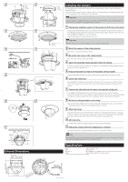
176 (6.93) 92 (3.62) 10 (0.39) 2 Fixing 3 screw M3 x 4 (included) 4 5 6 7 8 9 10 11 Secure to an anchor or structure Ceiling bracket Dome Camera Safety wire LAN cable Backside ceiling bracket Ceiling board External Dimensions 162 (6.38) (Max. circumscribed exterior dimension) (R2.R446)2 204 (8.03) 3(-ce4ili.n6g(m0ou.1n8t h)oles) Fixing screw M3 x 3 (included) Ceiling bracket screw M4 x 3 (included) Installing the Camera The procedures for mounting the camera to the ceiling using the indoor dome housing are described below. If using an memory card, insert the memory card into the camera before installing (please refer to the "Installation Guide" included with the camera). Important Once the camera is installed to the ceiling, to insert and remove the memory card, the camera must be removed from the ceiling and the ceiling bracket dismounted. 1 Determine an installation position for the camera and drill holes in the ceiling Using the included template, line up the directon of the camera, determine the locations of the backside ceiling bracket mounting holes (three) and the ceiling bracket holes, then drill the holes ( 165 mm ( 6.50 in.)) into the ceiling. Use the template with the printed side facing you. Important When mounting the indoor dome housing, be sure no shavings enter the dome. 2 Mount the camera to the ceiling bracket Affix with four included fixing screw (M3). 3 Mount the dust cover to the ceiling bracket Affix with three included fixing screw (M3). 4 Attach the backside ceiling brackets inside the ceiling From the inside of the ceiling, insert the protrusions on the backside ceiling brackets through the mounting holes drilled in step 1. 5 Temporarily tighten screws to the backside ceiling bracket Temporarily tighten the three included ceiling bracket screws (M4) through the ceiling. 6 Secure the safety wire Securely attach the safety wire to an anchor or structure. After securing one end of the safety wire to the ceiling, secure the other end to the camera using the screw that is fastened to the camera. 7 Connect the LAN cable to the camera through the wiring hole If AC Adapter (sold separately) or an external power supply is used, connect the power connector to the camera. Connect cables to external device I/O terminals and audio input/output terminals as necessary (please refer to the "Installation Guide" included with the camera). 8 Mount the ceiling bracket on the ceiling Position the ceiling bracket over the screws temporarily tightened in step 5, turn clockwise to temporarily secure in place, and completely fasten the screws. 9 Attach the dome Align the (O) mark on the dome with the (I) mark on the ceiling bracket, and turn clockwise until the (I) mark on the dome aligns with the (I) mark on the ceiling bracket. This procedure also aligns the ceiling bracket screw hole with the dome fixing screw hole. 10 Affix the dome To prevent the dome from rotating, attach one dome fixing screw (M2). 11 Reboot the camera when the installation is complete The camera position is initialized (please refer to the "Operation Guide"). Note While the LED is on, light may reflect inside the dome and be captured on video. If this happens, set the LED setting to [Turn Off] (please refer to the "Operation Guide"). 120° 182 ( 7.17) 7( 0.28) Specifications Model DR41-C-VB/DR41-S-VB Type Clear/Smoked * Dimensions ( x H) 204 x 176 mm ( 8.03 x 6.93 in.) (Dome: R62 mm (R2.44 in.)) Weight Approx. 765 g (1.687 lb.) (excluding camera) * This dome is approximately 50% transparent. Unit: mm (in.)
-
 1
1 -
 2
2
 |
 |
