Cisco 2950C-24 Hardware Installation Guide - Page 41
Rear-Panel Description - 2950g 24 ei
 |
UPC - 746320454481
View all Cisco 2950C-24 manuals
Add to My Manuals
Save this manual to your list of manuals |
Page 41 highlights
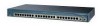
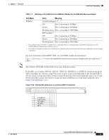
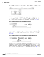
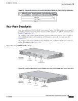
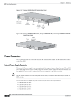
Chapter 1 Overview Rear-Panel Description Figure 1-24 Bandwidth Utilization on Catalyst 2950G-48-EI, 2950SX-48-SI, and 2950T-48-SI Switches 65510 Catalyst 2950 12 1X 3 24 56 78 9 10 11 12 13 14 15 16 15X 17 18 17X 19 20 21 22 23 24 25 26 27 28 29 31 31 32 31X 33 34 33X 35 36 37 38 39 40 41 42 43 44 45 46 47 48 47X 1 SYST RPS STAT UTIL DUPLX SPEED 2X MODE 16X 18X 32X 34X 2 48X < 25% + 25% - 49% + 50% + Rear-Panel Description Other than the Catalyst 2950G-24-EI-DC switch and the Catalyst 2950 LRE switches, the rear panel of a Catalyst 2950 switch has an AC power connector, an RPS connector, and an RJ-45 console port. (See Figure 1-25 and Figure 1-26.) The rear panel of the Catalyst 2950G-24-EI-DC switch has a DC power connector (also referred to as the terminal block header), a DC ground lug, an RPS connector, and an RJ-45 console port. (See Figure 1-27.) The rear panel of the Catalyst 2950ST-8 LRE, 2950ST-24 LRE, and 2950ST-24 LRE 997 switches has only an RPS connector. (See Figure 1-28.) Figure 1-25 Catalyst 2950 Switch Rear Panel 45585 12005R@[email protected]~~ AC power connector [email protected]. CONSOLE RPS connector Fan RJ-45 console port Figure 1-26 Catalyst 2950G-48-EI, Catalyst 2950SX-48-SI, and Catalyst 2950T-48-SI Switch Rear Panel 65511 12005R@[email protected]~~ AC power connector [email protected]. RPS connector Fan exhaust CONSOLE RJ-45 console port OL-6156-01 Catalyst 2950 Switch Hardware Installation Guide 1-21
-
 1
1 -
2
-
3
-
4
-
5
-
6
-
7
-
8
-
9
-
10
-
11
-
12
-
13
-
14
-
15
-
16
-
17
-
18
-
19
-
20
-
21
-
22
-
23
-
24
-
25
-
26
-
27
-
28
-
29
-
30
-
31
-
32
-
33
-
34
-
35
-
 36
36 -
 37
37 -
 38
38 -
 39
39 -
 40
40 -
 41
41 -
 42
42 -
 43
43 -
 44
44 -
 45
45 -
 46
46 -
47
-
48
-
49
-
50
-
51
-
52
-
53
-
54
-
55
-
56
-
57
-
58
-
59
-
60
-
61
-
62
-
63
-
64
-
65
-
66
-
67
-
68
-
69
-
70
-
71
-
72
-
73
-
74
-
75
-
76
-
77
-
78
-
79
-
80
-
81
-
82
-
83
-
84
-
85
-
86
-
87
-
88
-
89
-
90
-
91
-
92
-
93
-
94
-
95
-
96
-
97
-
98
-
99
-
100
-
101
-
102
-
103
-
104
-
105
-
106
-
107
-
108
-
109
-
110
-
111
-
112
-
113
-
114
-
115
-
116
-
117
-
118
-
119
-
120
-
121
-
122
-
123
-
124
-
125
-
126
-
127
-
128
-
129
-
130
-
131
-
132
-
133
-
134
 |
 |
