Cisco 2960-48TT Hardware Installation Guide - Page 71
Removing the Ground-Lug Screws, Step 2
 |
UPC - 882658044014
View all Cisco 2960-48TT manuals
Add to My Manuals
Save this manual to your list of manuals |
Page 71 highlights
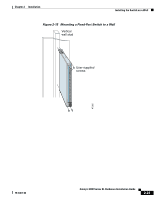
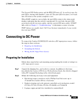
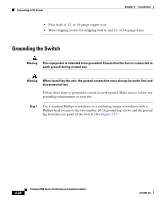
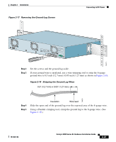
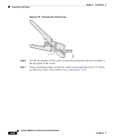
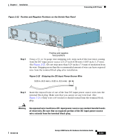
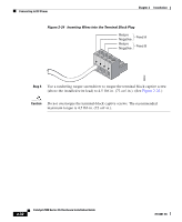
Chapter 2 Installation Figure 2-17 Removing the Ground-Lug Screws Connecting to DC Power CONSOLE BERFEOFREERPOCTOWONEMNRAENCUTAINL G DC INPUT ICNUPRURTE: 3N6T:- 72 4-2A A +- B +- 74071 Step 2 Step 3 Set the screws and the ground lug aside. If your ground wire is insulated, use a wire-stripping tool to strip the 6-gauge ground wire to 0.5 inch (12.7 mm) ±0.05 inch (1.27 mm) as shown in Figure 2-18: Figure 2-18 Stripping the Ground-Lug Wires 0.5" (12.7 mm) ± 0.05" (1.27 mm) 74076 Step 4 Step 5 Insulation Wire lead Slide the open end of the ground lug over the exposed area of the 6-gauge wire. Using a Panduit crimping tool, crimp the ground lug to the 6-gauge wire. (See Figure 2-19.) 78-6461-04 Catalyst 2900 Series XL Hardware Installation Guide 2-27
-
 1
1 -
2
-
3
-
4
-
5
-
6
-
7
-
8
-
9
-
10
-
11
-
12
-
13
-
14
-
15
-
16
-
17
-
18
-
19
-
20
-
21
-
22
-
23
-
24
-
25
-
26
-
27
-
28
-
29
-
30
-
31
-
32
-
33
-
34
-
35
-
36
-
37
-
38
-
39
-
40
-
41
-
42
-
43
-
44
-
45
-
46
-
47
-
48
-
49
-
50
-
51
-
52
-
53
-
54
-
55
-
56
-
57
-
58
-
59
-
60
-
61
-
62
-
63
-
64
-
65
-
 66
66 -
 67
67 -
 68
68 -
 69
69 -
 70
70 -
 71
71 -
 72
72 -
 73
73 -
 74
74 -
 75
75 -
 76
76 -
77
-
78
-
79
-
80
-
81
-
82
-
83
-
84
-
85
-
86
-
87
-
88
-
89
-
90
-
91
-
92
-
93
-
94
-
95
-
96
-
97
-
98
-
99
-
100
-
101
-
102
-
103
-
104
-
105
-
106
-
107
-
108
-
109
-
110
-
111
-
112
-
113
-
114
-
115
-
116
-
117
-
118
-
119
-
120
-
121
-
122
-
123
-
124
-
125
-
126
-
127
-
128
-
129
-
130
-
131
-
132
-
133
-
134
-
135
-
136
-
137
-
138
-
139
-
140
-
141
-
142
-
143
-
144
-
145
-
146
-
147
-
148
-
149
-
150
-
151
-
152
-
153
-
154
-
155
-
156
-
157
-
158
-
159
-
160
-
161
-
162
 |
 |
