Cisco AIR-AP1131AG-N-K9 Hardware Installation Guide - Page 56
Replacing the Back Cover
 |
View all Cisco AIR-AP1131AG-N-K9 manuals
Add to My Manuals
Save this manual to your list of manuals |
Page 56 highlights
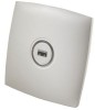
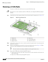
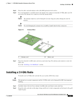
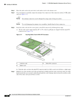
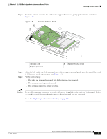
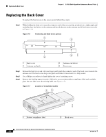
Replacing the Back Cover Chapter 4 2.4-GHz Radio Upgrade for Autonomous Access Points Replacing the Back Cover To replace the back cover on the access point, follow these steps: Step 1 While holding the back cover near the connector end of the access point, position it at a slight angle and carefully place the latches on the antenna end into the detents on the antenna end of the front cover (refer to Figure 4-6). Figure 4-6 Positioning the Back Cover Latches 1 2 97572 3 4 1 Back cover 2 Antenna end latch 3 Antenna end detent 4 Front cover Step 2 Step 3 Step 4 Release the back cover and with one finger gently push the connector end of the back cover towards the antenna end. The back cover drops into place and slides forward until it is fully seated. Use a Philips screwdriver to hand tighten the cover's retaining screw. Remove the backing paper from the 1100 series access point product compliance label and carefully place the new label over the existing label (see Figure 4-7). Figure 4-7 Location of Compliance Labels 1 2 95756 1 Product compliance label 2 Back cover Cisco Aironet 1100 Series Access Point Hardware Installation Guide 4-8 OL-4309-07
-
 1
1 -
2
-
3
-
4
-
5
-
6
-
7
-
8
-
9
-
10
-
11
-
12
-
13
-
14
-
15
-
16
-
17
-
18
-
19
-
20
-
21
-
22
-
23
-
24
-
25
-
26
-
27
-
28
-
29
-
30
-
31
-
32
-
33
-
34
-
35
-
36
-
37
-
38
-
39
-
40
-
41
-
42
-
43
-
44
-
45
-
46
-
47
-
48
-
49
-
50
-
 51
51 -
 52
52 -
 53
53 -
 54
54 -
 55
55 -
 56
56 -
 57
57 -
 58
58 -
 59
59 -
 60
60 -
 61
61 -
62
-
63
-
64
-
65
-
66
-
67
-
68
-
69
-
70
-
71
-
72
-
73
-
74
-
75
-
76
-
77
-
78
-
79
-
80
-
81
-
82
-
83
-
84
-
85
-
86
-
87
-
88
-
89
-
90
-
91
-
92
-
93
-
94
-
95
-
96
-
97
-
98
-
99
-
100
-
101
-
102
-
103
-
104
-
105
-
106
-
107
-
108
-
109
-
110
-
111
-
112
-
113
-
114
-
115
-
116
 |
 |