Cisco AIR-BR1310G-A-K9-R Data Sheet - Page 5
Cisco Aironet 1300 Series, Power Injector, Data Sheet, Network Diagram with Power Injector - specifications
 |
UPC - 746320927459
View all Cisco AIR-BR1310G-A-K9-R manuals
Add to My Manuals
Save this manual to your list of manuals |
Page 5 highlights
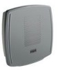
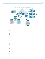
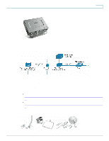
Figure 3. Network Diagram with Power Injector Data Sheet Cisco Aironet 1300 Series The Cisco Aironet 1300 Series provides the 802.11g interface for access-point capability or bridge connections. By placing the unit outdoors, close to the antenna, you can minimize the wireless cable losses-thereby maximizing the range of the network. The unit is available with either an integrated antenna, or with connectors for external antennas (Figure 4). The high-gain, integrated antenna is designed for easy installations of point-to-point links or non-root nodes of point-to-multipoint networks as an autonomous bridge. The nonintegrated antenna version provides professional installers with an RP-TNC connector that allows the deployment of omnidirectional, sector, or high-gain dish antennas for specific application requirements. Figure 4. Cisco Aironet 1300 Series Connector Options Power Injector The Cisco Aironet Bridge Power Injector converts the standard 10/100BASE-T Ethernet interface that is suitable for weather-protected areas to a dual F-Type connector interface for coaxial cables that are more suitable for harsh outdoor environments. The power injector also provides power to the outdoor unit over the same cables with a power-discover feature and surge protection. To support longer cabling from your wired switch or router, the power injector enables total cable runs up to 200 meters (Category 5 [Cat5] and coaxial). The Cisco Aironet 1300 Series ships with the Cisco Aironet Power Injector LR2 (Figure 5) and an AC power supply. © 2009 Cisco Systems, Inc. All rights reserved. This document is Cisco Public Information. Page 5 of 14
-
 1
1 -
 2
2 -
 3
3 -
 4
4 -
 5
5 -
 6
6 -
 7
7 -
 8
8 -
 9
9 -
 10
10 -
 11
11 -
12
-
13
-
14
 |
 |
