Cisco AIR-BR350-E-K9 Hardware Installation Guide - Page 27
Series Bridge Power Options
 |
View all Cisco AIR-BR350-E-K9 manuals
Add to My Manuals
Save this manual to your list of manuals |
Page 27 highlights
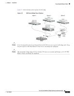
Chapter 2 Installation Connecting the Ethernet Cables Figure 2-2 shows the three power options for the bridge. Figure 2-2 350 Series Bridge Power Options Option 1 Switch with inline power SYST RPS STAT UTIL DUPLX SPEED MODE 1 2 3 4 5 6 7 8 9 10 11 10Base-T / 100Base-TX 12 13 14 15 16 17 18 19 20 21 22 23 Catalyst 2950 SERIES 24 100Base-FX 23 24 Option 2 Switch (without inline power) SYST RPS STAT UTIL DUPLX SPEED MODE 1 2 3 4 5 6 7 8 9 10 11 10Base-T / 100Base-TX 12 13 14 15 16 17 18 19 20 21 22 23 Catalyst 2950 SERIES 24 100Base-FX 23 24 Inline Power Patch Panel SYST RPS STAT UTIL DUPLX SPEED MODE Option 3 Switch (without inline power) SYST RPS STAT UTIL DUPLX SPEED MODE 1 2 3 4 5 6 7 8 9 10 11 10Base-T / 100Base-TX 12 13 14 15 16 17 18 19 20 21 22 23 Catalyst 2950 SERIES 24 21300Base-FX24 Power injector AP/ BRITDOGE NETWOTROK W I RCEILSECSOS AAICRCOE SN SETP 3O I50N STERIES RADIOAASCSTIOVCIEITTAYTHIEORNNSETTATAUCSTIVITY LEFT SERIAL PORT ONLINE POWER ETHERNET RIGHT/PRIMARY Bridge Power cord Universal power supply Caution Cisco Aironet power injectors are designed for use with 350 series access points and bridges only. Using the power injector with other Ethernet-ready devices can damage the equipment. Caution The operational voltage range for Cisco Aironet 350 series access points and bridges is 24 to 60 VDC. Higher voltage can damage the equipment. OL-1412-01 Cisco Aironet 350 Series Bridge Hardware Installation Guide 2-7
-
 1
1 -
2
-
3
-
4
-
5
-
6
-
7
-
8
-
9
-
10
-
11
-
12
-
13
-
14
-
15
-
16
-
17
-
18
-
19
-
20
-
21
-
 22
22 -
 23
23 -
 24
24 -
 25
25 -
 26
26 -
 27
27 -
 28
28 -
 29
29 -
 30
30 -
 31
31 -
 32
32 -
33
-
34
-
35
-
36
-
37
-
38
-
39
-
40
-
41
-
42
-
43
-
44
-
45
-
46
-
47
-
48
-
49
-
50
-
51
-
52
-
53
-
54
-
55
-
56
-
57
-
58
-
59
-
60
-
61
-
62
-
63
-
64
-
65
-
66
-
67
-
68
-
69
-
70
-
71
-
72
-
73
-
74
-
75
-
76
 |
 |
