Cisco AIR-RM1252G-A-K9= Hardware Installation Guide - Page 48
Connecting the Ethernet and Power Cables - radio air
 |
UPC - 882658140860
View all Cisco AIR-RM1252G-A-K9= manuals
Add to My Manuals
Save this manual to your list of manuals |
Page 48 highlights
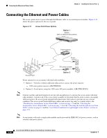
Connecting the Ethernet and Power Cables Chapter 2 Installing the Access Point Connecting the Ethernet and Power Cables The access point receives power through the Ethernet cable or an external power module. Figure 2-14 shows the power options for the access point. Figure 2-14 Access Point Power Options Option 1 Switch (with or without inline power) SYST RPS STAT UTIL DUPLX SPEED MODE 1 2 3 4 5 6 7 8 9 10 11 10Base-T / 100Base-TX 12 13 14 15 16 17 18 19 20 21 22 23 Catalyst 2950 SERIES 24 100Base-FX 23 24 Power injector Power cord DC power module 230559 Access Point Option 2 Power options for access points with dual radio modules: • Option 1-Switches without sufficient inline power can use the power injector: - 1250 series power injector (AIR-PWRINJ4) • Option 2-Local power using the 1250 series DC power module (AIR-PWR-SPLY1) Note Current switches and patch panels do not provide enough power to operate the access point with dual radio modules. At power-up, if the access point is unable to determine that the power source can supply sufficient power, the access point automatically deactivates both radios to prevent an over-current condition. The access point Status LED turns amber and an error log entry is created (refer to the "Checking the Autonomous Access Point LEDs" section on page 3-2 and the "Checking the Autonomous Access Point LEDs" section on page 3-2) or the "Checking the Lightweight Access Point LEDs" section on page 4-3 and the "Low Power Condition for Lightweight Access Points" section on page 4-7). Note Access points with only a single radio module can be powered by IEEE 802.3af power sources, such as switches and power panels. 2-20 Cisco Aironet 1250 Series Access Point Hardware Installation Guide OL-8247-03
-
 1
1 -
2
-
3
-
4
-
5
-
6
-
7
-
8
-
9
-
10
-
11
-
12
-
13
-
14
-
15
-
16
-
17
-
18
-
19
-
20
-
21
-
22
-
23
-
24
-
25
-
26
-
27
-
28
-
29
-
30
-
31
-
32
-
33
-
34
-
35
-
36
-
37
-
38
-
39
-
40
-
41
-
42
-
 43
43 -
 44
44 -
 45
45 -
 46
46 -
 47
47 -
 48
48 -
 49
49 -
 50
50 -
 51
51 -
 52
52 -
 53
53 -
54
-
55
-
56
-
57
-
58
-
59
-
60
-
61
-
62
-
63
-
64
-
65
-
66
-
67
-
68
-
69
-
70
-
71
-
72
-
73
-
74
-
75
-
76
-
77
-
78
-
79
-
80
-
81
-
82
-
83
-
84
-
85
-
86
-
87
-
88
-
89
-
90
-
91
-
92
-
93
-
94
-
95
-
96
-
97
-
98
-
99
-
100
-
101
-
102
-
103
-
104
-
105
-
106
-
107
-
108
-
109
-
110
-
111
-
112
-
113
-
114
-
115
-
116
-
117
-
118
-
119
-
120
-
121
-
122
-
123
-
124
-
125
-
126
-
127
-
128
-
129
-
130
-
131
-
132
-
133
-
134
-
135
-
136
-
137
-
138
-
139
-
140
-
141
-
142
 |
 |
