Cisco ASR1006-10G-VPN/K9 Installation Guide
Cisco ASR1006-10G-VPN/K9 - ASR 1006 VPN Bundle Router Manual
 |
View all Cisco ASR1006-10G-VPN/K9 manuals
Add to My Manuals
Save this manual to your list of manuals |
Cisco ASR1006-10G-VPN/K9 manual content summary:
- Cisco ASR1006-10G-VPN/K9 | Installation Guide - Page 1
midplane with connectors on one interface midplane. The Cisco ASR 1006 Router supports: • Three Cisco ASR 1000 Series SPA Interface Processor (SIP) • Twelve SPA slots • Three Cisco ASR 1000 Series Embedded Services Processor (Cisco ASR1000-ESP10, Cisco ASR1000-ESP20, and also Cisco ASR1000-ESP40 - Cisco ASR1006-10G-VPN/K9 | Installation Guide - Page 2
ASR 1000 Series ESP 5 ASR 1000 Series SIP slot 0 6 ASR 1000 Series SIP slot 1 7 ASR 1000 Series SIP slot 2 280032 Cisco ASR 1000 Series Aggregation Services Routers Hardware Installation Guide 6-2 OL-13208-09 - Cisco ASR1006-10G-VPN/K9 | Installation Guide - Page 3
25 sub connector which enables you to attach an external alarm monitoring facility to the router, thus supporting a telco-style of handling alarm conditions in the router. For a description of the DB-25 OL-13208-09 Cisco ASR 1000 Series Aggregation Services Routers Hardware Installation Guide 6-3 - Cisco ASR1006-10G-VPN/K9 | Installation Guide - Page 4
the Regulatory Compliance and Safety Information for Cisco ASR 1000 Series Aggregation Services Routers publication. This document provides important safety information you should know the installation. Cisco ASR 1000 Series Aggregation Services Routers Hardware Installation Guide 6-4 OL-13208-09 - Cisco ASR1006-10G-VPN/K9 | Installation Guide - Page 5
0 6 ASR 1000 Series SIP slot 1 7 ASR 1000 Series SIP slot 2 -- The Cisco ASR 1006 Router contains three Cisco ASR 1000 Series SPA Interface (SIP) supports four subslots for the installation of SPAs. OL-13208-09 Cisco ASR 1000 Series Aggregation Services Routers Hardware Installation Guide 6-5 - Cisco ASR1006-10G-VPN/K9 | Installation Guide - Page 6
unit (1.75 inch or 4.45 cm) of vertical clearance between the chassis and any equipment directly above it or below. Cisco ASR 1000 Series Aggregation Services Routers Hardware Installation Guide 6-6 OL-13208-09 - Cisco ASR1006-10G-VPN/K9 | Installation Guide - Page 7
1006 Router needs adequate ventilation. Do not install it in an enclosed cabinet where ventilation is inadequate. OL-13208-09 Cisco ASR 1000 Series Aggregation Services Routers Hardware Installation Guide 6-7 - Cisco ASR1006-10G-VPN/K9 | Installation Guide - Page 8
3 on the other side of the chassis. Use at least 4 screws to secure the rack-mount brackets to the chassis. Cisco ASR 1000 Series Aggregation Services Routers Hardware Installation Guide 6-8 OL-13208-09 - Cisco ASR1006-10G-VPN/K9 | Installation Guide - Page 9
, use two screws from the package of four screws. Ensure that all the screws are securely tightened. OL-13208-09 Cisco ASR 1000 Series Aggregation Services Routers Hardware Installation Guide 6-9 - Cisco ASR1006-10G-VPN/K9 | Installation Guide - Page 10
Go to the "Attaching a Chassis Ground Connection" section on page 6-19 for instructions about completing the installation. Rack-Mounting the Cisco ASR 1006 Router The Cisco ASR cm ± 0.15 cm) 28014 6-10 Cisco ASR 1000 Series Aggregation Services Routers Hardware Installation Guide OL-13208-09 - Cisco ASR1006-10G-VPN/K9 | Installation Guide - Page 11
rack-mount bracket screws 2 Front rack-mount bracket 4 32 1 3 Front rack-mount bracket ear and holes 4 Chassis side vent location Cisco ASR 1000 Series Aggregation Services Routers Hardware Installation Guide 6-11 - Cisco ASR1006-10G-VPN/K9 | Installation Guide - Page 12
the rear t rack-mount bracket with the ear and holes facing outward and towards the rear of the chassis. 6-12 Cisco ASR 1000 Series Aggregation Services Routers Hardware Installation Guide OL-13208-09 - Cisco ASR1006-10G-VPN/K9 | Installation Guide - Page 13
rack. Installation of the cable-management bracket is simplified when you use the designated ear holes on the rack-mount bracket. For cable-management installation instructions, see the "Attaching the Cable-Management Brackets" section on page 6-18. OL-13208-09 Cisco ASR 1000 Series Aggregation - Cisco ASR1006-10G-VPN/K9 | Installation Guide - Page 14
of the shelf. Let the bottom of the chassis rest on the brackets, but continue to support the chassis. Step 6 Step 7 Position the chassis until the rack-mounting flanges are flush against chassis. 6-14 Cisco ASR 1000 Series Aggregation Services Routers Hardware Installation Guide OL-13208-09 - Cisco ASR1006-10G-VPN/K9 | Installation Guide - Page 15
F0 R1 R0 2 1 280085 1 Cisco ASR 1006 Router front rack-mount bracket 2 Two-post equipment rack rail OL-13208-09 Cisco ASR 1000 Series Aggregation Services Routers Hardware Installation Guide 6-15 - Cisco ASR1006-10G-VPN/K9 | Installation Guide - Page 16
: • Installing the chassis in an existing rack with equipment. • Installing an empty chassis in a rack with no equipment installed. 6-16 Cisco ASR 1000 Series Aggregation Services Routers Hardware Installation Guide OL-13208-09 - Cisco ASR1006-10G-VPN/K9 | Installation Guide - Page 17
rack is stabilized. Step 1 (Optional) Install a shelf in the rack to support the Cisco ASR 1006 Router. If you are using a shelf then raise the chassis Let the bottom of the chassis rest on the brackets, but continue to support the chassis.Using two people, lift the chassis into the rack using the - Cisco ASR1006-10G-VPN/K9 | Installation Guide - Page 18
bottom rack-mount ear hole, insert the screw through the cable-management bracket and into the rack-mount bracket. 6-18 Cisco ASR 1000 Series Aggregation Services Routers Hardware Installation Guide OL-13208-09 - Cisco ASR1006-10G-VPN/K9 | Installation Guide - Page 19
SPA must be fully inserted and screwed in and earthed to prevent a potential hazard in a telecom line. OL-13208-09 Cisco ASR 1000 Series Aggregation Services Routers Hardware Installation Guide 6-19 - Cisco ASR1006-10G-VPN/K9 | Installation Guide - Page 20
supplies necessary to connect the system ground to the chassis: • Phillips screwdriver • Dual-lug chassis ground component • Grounding wire 6-20 Cisco ASR 1000 Series Aggregation Services Routers Hardware Installation Guide OL-13208-09 - Cisco ASR1006-10G-VPN/K9 | Installation Guide - Page 21
sections for information on attaching cables. Connecting the Shared Port Adapter Cables The instructions for connecting the cables for the shared port adapter installed in the Cisco ASR /paposoc3.html OL-13208-09 Cisco ASR 1000 Series Aggregation Services Routers Hardware Installation Guide 6-21 - Cisco ASR1006-10G-VPN/K9 | Installation Guide - Page 22
a fixed speed (10 or 100 Mbps) through command-line interface (CLI) commands, the port is forced to MDI mode. 6-22 Cisco ASR 1000 Series Aggregation Services Routers Hardware Installation Guide OL-13208-09 - Cisco ASR1006-10G-VPN/K9 | Installation Guide - Page 23
Statement 1003 Warning Only trained and qualified personnel should be allowed to install, replace, or service this equipment. Statement wire for a 30 A circuit breaker. Power Cords Supported by the Cisco ASR 1006 Router The following power cords are supported by the Cisco ASR 1006 Router: • CAB- - Cisco ASR1006-10G-VPN/K9 | Installation Guide - Page 24
IEC-C19 14ft US The Cisco ASR 1006 Router modular chassis supports redundant power entry modules (PEMs). In the Cisco ASR 1006 circuit that does not exceed 20 A. Note Detailed instructions for removing and replacing the Cisco ASR 1000 Series Services Routers Hardware Installation Guide OL-13208-09 - Cisco ASR1006-10G-VPN/K9 | Installation Guide - Page 25
5 AC power supply handle 6 AC power inlet 7 AC power supply Standby switch 8 AC power supply LEDs 280029 OL-13208-09 Cisco ASR 1000 Series Aggregation Services Routers Hardware Installation Guide 6-25 - Cisco ASR1006-10G-VPN/K9 | Installation Guide - Page 26
supply captive screw 5 AC power supply handle 6 AC power inlet 7 AC power supply Standby switch 8 Protective shielding on both sides of the Standby switch 9 AC power supply LEDs Step 3 Plug the AC power 26 Cisco ASR 1000 Series Aggregation Services Routers Hardware Installation Guide OL-13208-09 - Cisco ASR1006-10G-VPN/K9 | Installation Guide - Page 27
terminal and plastic cover 9 DC power supply On (|) /Off (O) switch 5 Grounding symbol 10 DC power supply LEDs OL-13208-09 Cisco ASR 1000 Series Aggregation Services Routers Hardware Installation Guide 6-27 - Cisco ASR1006-10G-VPN/K9 | Installation Guide - Page 28
the appropriate wire gauge based on the National Electrical Code (NEC) and local codes for 40-amp service at nominal DC input voltage (-48/-60 VDC). Three pairs of cable leads, source DC (-) and . 6-28 Cisco ASR 1000 Series Aggregation Services Routers Hardware Installation Guide OL-13208-09 - Cisco ASR1006-10G-VPN/K9 | Installation Guide - Page 29
the DC cable lugs, be sure to insulate the lugs according to the manufacturer's instructions. Warning When you install the unit, the ground connection must always be made first order. - Flat washer OL-13208-09 Cisco ASR 1000 Series Aggregation Services Routers Hardware Installation Guide 6-29 - Cisco ASR1006-10G-VPN/K9 | Installation Guide - Page 30
stud 2 Positive lug and wire with sleeving wrapped 4 Ground lug and wire around the wire and end of lug 6-30 Cisco ASR 1000 Series Aggregation Services Routers Hardware Installation Guide OL-13208-09 - Cisco ASR1006-10G-VPN/K9 | Installation Guide - Page 31
tighten the screw. The plastic cover is slotted and keyed to fit correctly over the terminal block. OL-13208-09 Cisco ASR 1000 Series Aggregation Services Routers Hardware Installation Guide 6-31 - Cisco ASR1006-10G-VPN/K9 | Installation Guide - Page 32
supply connection. All connections must be remov 3 1 Negative lead 2 Positive lead 3 Plastic cover slotted area 4 Terminal block plastic cover 6-32 Cisco ASR 1000 Series Aggregation Services Routers Hardware Installation Guide OL-13208-09 - Cisco ASR1006-10G-VPN/K9 | Installation Guide - Page 33
crossover cable • One RJ-45 to DB-25 (female) adapter • One RJ-45 to DB-9 (female) adapter OL-13208-09 Cisco ASR 1000 Series Aggregation Services Routers Hardware Installation Guide 6-33 - Cisco ASR1006-10G-VPN/K9 | Installation Guide - Page 34
280094 CARRIER LINK MGMT ETHERNET BITS AUX CON CARRIER LINK MGMT ETHERNET BITS AUX CON 1 CONsole port 2 AUXiliary port 6-34 Cisco ASR 1000 Series Aggregation Services Routers Hardware Installation Guide OL-13208-09 - Cisco ASR1006-10G-VPN/K9 | Installation Guide - Page 35
-power lines with any interface cables. • Verify all cabling limitations (particularly distance) before powering on the system. OL-13208-09 Cisco ASR 1000 Series Aggregation Services Routers Hardware Installation Guide 6-35 - Cisco ASR1006-10G-VPN/K9 | Installation Guide - Page 36
completed all the cable connections, go to Chapter 12, "Cisco ASR 1000 Series Routers Power Up and Initial Configuration." 6-36 Cisco ASR 1000 Series Aggregation Services Routers Hardware Installation Guide OL-13208-09
-
 1
1 -
 2
2 -
 3
3 -
 4
4 -
 5
5 -
 6
6 -
 7
7 -
8
-
9
-
10
-
11
-
12
-
13
-
14
-
15
-
16
-
17
-
18
-
19
-
20
-
21
-
22
-
23
-
24
-
25
-
26
-
27
-
28
-
29
-
30
-
31
-
32
-
33
-
34
-
35
-
36
 |
 |

CH A P T E R
6-1
Cisco ASR 1000 Series Aggregation Services Routers Hardware Installation Guide
OL-13208-09
6
Cisco ASR 1006 Router Overview and Installation
This chapter describes the Cisco ASR 1006 Router and the procedures for installing the Cisco
ASR 1006
Router on an equipment shelf or in equipment racks. It also describes how to connect interface and power
cables.
This chapter contains the following sections:
•
Cisco ASR 1006 Router Description, page 6-1
•
Installation Methods, page 6-6
•
General Rack Installation Guidelines, page 6-6
•
Guidelines for an Equipment Shelf or Tabletop Installation, page 6-7
•
Equipment Shelf or Tabletop Installation, page 6-8
•
Rack-Mounting the Cisco ASR 1006 Router, page 6-10
•
Attaching the Chassis Rack-Mount Brackets, page 6-11
•
Installing the Cisco ASR 1006 Router in a Rack, page 6-14
•
Attaching the Cable-Management Brackets, page 6-18
•
Attaching a Chassis Ground Connection, page 6-19
•
Connecting the Shared Port Adapter Cables, page 6-21
•
Connecting the Console and Auxiliary Port Cables, page 6-22
•
Connecting Power to the Cisco ASR 1006 Router, page 6-23
•
Connecting a Terminal to the Cisco ASR 1000 Series RP Console Port, page 6-33
•
Connecting the System Cables, page 6-35
•
Auxiliary Connection, page 6-36
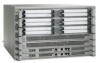
Cisco ASR 1006 Router Description
The Cisco ASR 1006 Router supports full-width card modules. It is designed with a single midplane with
connectors on one interface midplane. The Cisco ASR 1006 Router supports:
•
Three Cisco ASR 1000 Series SPA Interface Processor (SIP)
•
Twelve SPA slots
•
Three Cisco ASR 1000 Series Embedded Services Processor (Cisco ASR1000-ESP10, Cisco
ASR1000-ESP20, and also Cisco ASR1000-ESP40 with a Cisco ASR1000-RP2)