Cisco ASR1006-10G-VPN/K9 Installation Guide - Page 10
Rack-Mounting the Cisco ASR 1006 Router, Verifying Rack Dimensions
 |
View all Cisco ASR1006-10G-VPN/K9 manuals
Add to My Manuals
Save this manual to your list of manuals |
Page 10 highlights
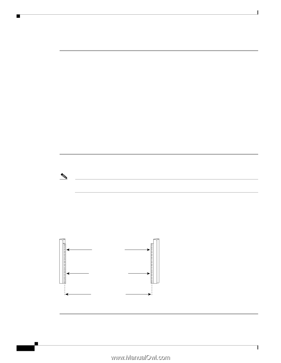
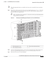
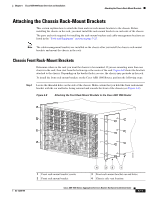
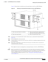
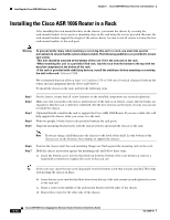
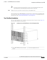
Rack-Mounting the Cisco ASR 1006 Router Chapter 6 Cisco ASR 1006 Router Overview and Installation Step 8 Go to the "Attaching a Chassis Ground Connection" section on page 6-19 for instructions about completing the installation. Rack-Mounting the Cisco ASR 1006 Router The Cisco ASR 1006 Router can be installed with both front or rear rack-mount brackets. The chassis rack-mounting flanges are secured directly to the chassis before you lift it into the rack. For installing Cisco ASR 1006 Router rack-mount brackets, go to: • Chassis Front Rack-Mount Brackets, page 6-11 • Chassis Rear Rack-Mount Brackets, page 6-12 Verifying Rack Dimensions Before you install the chassis, measure the space between the vertical mounting flanges (rails) on your equipment rack to verify that the rack conforms to the measurements shown in Figure 6-7. Step 1 Mark and measure the distance between two holes on the left and right mounting rails. The distance should measure 18.31 inches ± 0.06 inches (46.5 cm ± 0.15 cm). Note Measure for pairs of holes near the bottom, middle and top of the equipment rack to ensure that the rack posts are parallel. Step 2 Measure the space between the inner edges of the left front and right front mounting flanges on the equipment rack. The space must be at least 17.7 inches (45 cm) to accommodate the chassis which is 17.25 inches (43.8 cm) wide and fits between the mounting posts on the rack. Figure 6-7 Verifying Equipment Rack Dimensions Mounting flanges Minimum usable aperture 17.7 inches (45.0 cm) Hole centerline to hole centerline 18.31 inches ± 0.06 inches (46.5 cm ± 0.15 cm) 28014 6-10 Cisco ASR 1000 Series Aggregation Services Routers Hardware Installation Guide OL-13208-09
-
 1
1 -
2
-
3
-
4
-
 5
5 -
 6
6 -
 7
7 -
 8
8 -
 9
9 -
 10
10 -
 11
11 -
 12
12 -
 13
13 -
 14
14 -
 15
15 -
16
-
17
-
18
-
19
-
20
-
21
-
22
-
23
-
24
-
25
-
26
-
27
-
28
-
29
-
30
-
31
-
32
-
33
-
34
-
35
-
36
 |
 |