| Section |
Page |
| Cisco IOS Software Configuration Guide for Cisco Aironet Access Points |
1 |
| Preface |
21 |
| Audience |
21 |
| Purpose |
21 |
| Organization |
22 |
| Conventions |
23 |
| Related Publications |
25 |
| Obtaining Documentation, Obtaining Support, and Security Guidelines |
26 |
| 1 |
27 |
| Overview |
27 |
| Features |
28 |
| Features Introduced in This Release |
28 |
| Table 1-1 New Cisco IOS Software Features for Cisco IOS Release 12.4(10b)JA |
28 |
| Management Options |
28 |
| Roaming Client Devices |
29 |
| Network Configuration Examples |
29 |
| Root Access Point |
29 |
| Figure 1-1 Access Points as Root Units on a Wired LAN |
30 |
| Repeater Access Point |
30 |
| Figure 1-2 Access Point as Repeater |
30 |
| Bridges |
31 |
| Figure 1-3 Access Point as a Root Bridge with Clients |
31 |
| Figure 1-4 Access Points as Root and Non-root Bridges with Clients |
31 |
| Workgroup Bridge |
31 |
| Figure 1-5 Access Point as a Workgroup Bridge |
32 |
| Central Unit in an All-Wireless Network |
32 |
| Figure 1-6 Access Point as Central Unit in All-Wireless Network |
32 |
| 2 |
33 |
| Using the Web-Browser Interface |
33 |
| Using the Web-Browser Interface for the First Time |
35 |
| Step 1 Start the browser. |
35 |
| Step 2 Enter the wireless device’s IP address in the browser Location field (Netscape Communicator) or Address field (Internet Explorer) and press Enter. The Summary StatusHome page appears. |
35 |
| Using the Management Pages in the Web-Browser Interface |
35 |
| Figure 2-1 Web-Browser Interface Home Page |
35 |
| Using Action Buttons |
36 |
| Table 2-1 Common Buttons on Management Pages |
36 |
| Character Restrictions in Entry Fields |
37 |
| Enabling HTTPS for Secure Browsing |
37 |
| Step 1 If your browser uses popup-blocking software, disable the popup-blocking feature. |
38 |
| Step 2 Browse to the Express Setup page. Figure 2-2 shows the Express Setup page. |
38 |
| Figure 2-2 Express Setup Page |
38 |
| Step 3 Enter a name for the access point in the System Name field and click Apply. |
38 |
| Step 4 Browse to the Services - DNS page. Figure 2-3 shows the Services - DNS page. |
38 |
| Figure 2-3 Services - DNS Page |
39 |
| Step 5 Select Enable for Domain Name System. |
39 |
| Step 6 In the Domain Name field, enter your company’s domain name. At Cisco Systems, for example, the domain name is cisco.com. |
39 |
| Step 7 Enter at least one IP address for your DNS server in the Name Server IP Addresses entry fields. |
39 |
| Step 8 Click Apply. The access point’s FQDN is a combination of the system name and the domain name. For example, if your system name is ap1100 and your domain name is company.com, the FQDN is ap1100.company.com. |
39 |
| Step 9 Enter the FQDN on your DNS server. |
39 |
| Step 10 Browse to the Services: HTTP Web Server page. Figure 2-4 shows the HTTP Web Server page: |
40 |
| Figure 2-4 Services: HTTP Web Server Page |
40 |
| Step 11 Select the Enable Secure (HTTPS) Browsing check box and click Apply. |
40 |
| Step 12 Enter a domain name and click Apply. |
40 |
| Figure 2-5 HTTPS Warning Window |
40 |
| Step 13 Click OK. The address in your browser’s address line changes from http://ip-address to https://ip-address. |
40 |
| Step 14 Another warning window appears stating that the access point’s security certificate is valid but is not from a known sou... |
41 |
| Figure 2-6 Certificate Warning Window |
41 |
| Step 15 Click View Certificate to accept the certificate before proceeding. (To proceed without accepting the certificate, click Yes, and skip to Step 24 in these instructions.) Figure 2-7 shows the Certificate window. |
41 |
| Figure 2-7 Certificate Window |
42 |
| Step 16 On the Certificate window, click Install Certificate. The Microsoft Windows Certificate Import Wizard appears. Figure 2-8 shows the Certificate Import Wizard window. |
42 |
| Figure 2-8 Certificate Import Wizard Window |
43 |
| Step 17 Click Next. The next window asks where you want to store the certificate. Cisco recommends that you use the default storage area on your system. Figure 2-9 shows the window that asks about the certificate storage area. |
43 |
| Figure 2-9 Certificate Storage Area Window |
43 |
| Step 18 Click Next to accept the default storage area. A window appears that states that you successfully imported the certificate. Figure 2-10 shows the completion window. |
43 |
| Figure 2-10 Certificate Completion Window |
44 |
| Step 19 Click Finish. Windows displays a final security warning. Figure 2-11 shows the security warning. |
44 |
| Figure 2-11 Certificate Security Warning |
44 |
| Step 20 Click Yes. Windows displays another window stating that the installation is successful. Figure 2-12 shows the completion window. |
44 |
| Figure 2-12 Import Successful Window |
45 |
| Step 21 Click OK. |
45 |
| Step 22 On the Certificate window shown in Figure 2-7, which is still displayed, click OK. |
45 |
| Step 23 On the Security Alert window shown in Figure 2-6, click Yes. |
45 |
| Step 24 The access point login window appears and you must log into the access point again. The default user name is Cisco (case-sensitive) and the default password is Cisco (case-sensitive). |
45 |
| CLI Configuration Example |
45 |
| Deleting an HTTPS Certificate |
45 |
| Step 1 Browse to the Services: HTTP Web Server page. |
45 |
| Step 2 Uncheck the Enable Secure (HTTPS) Browsing check box to disable HTTPS. |
45 |
| Step 3 Click Delete Certificate to delete the certificate. |
45 |
| Step 4 Re-enable HTTPS. The access point generates a new certificate using the new FQDN. |
45 |
| Using Online Help |
46 |
| Figure 2-13 Help and Print Icons |
46 |
| Changing the Location of Help Files |
46 |
| Step 1 Download the help files from the Software Center on Cisco.com. Click this link to go to the Cisco Software Center home page: |
46 |
| Step 2 Unzip the help files on your network in a directory accessible to your access point. When you unzip the help files, the HTML help pages are stored in a folder named according to the help version number and access point model number. |
46 |
| Step 3 Browse to the Services: HTTP Web Server page in the access point web-browser interface. |
46 |
| Step 4 In the Default Help Root URL entry field, enter the complete path to the location where you unzipped the help files. When... |
46 |
| Table 2-2 Example Help Root URL and Help Location |
47 |
| Step 5 Click Apply. |
47 |
| Disabling the Web-Browser Interface |
47 |
| 3 |
49 |
| Using the Command-Line Interface |
49 |
| Cisco IOS Command Modes |
50 |
| Table 3-1 Command Mode Summary |
50 |
| Getting Help |
51 |
| Table 3-2 Help Summary |
51 |
| Abbreviating Commands |
51 |
| Using no and default Forms of Commands |
52 |
| Understanding CLI Messages |
52 |
| Table 3-3 Common CLI Error Messages |
52 |
| Using Command History |
52 |
| Changing the Command History Buffer Size |
53 |
| Recalling Commands |
53 |
| Table 3-4 Recalling Commands |
53 |
| Disabling the Command History Feature |
53 |
| Using Editing Features |
54 |
| Enabling and Disabling Editing Features |
54 |
| Editing Commands Through Keystrokes |
54 |
| Table 3-5 Editing Commands Through Keystrokes |
54 |
| Editing Command Lines that Wrap |
55 |
| Searching and Filtering Output of show and more Commands |
56 |
| Accessing the CLI |
57 |
| Opening the CLI with Telnet |
57 |
| Step 1 Select Start > Programs > Accessories > Telnet. |
57 |
| Step 2 When the Telnet window appears, click Connect and select Remote System. |
57 |
| Step 3 In the Host Name field, type the wireless device’s IP address and click Connect. |
57 |
| Step 4 At the username and password prompts, enter your administrator username and password. The default username is Cisco, and the default password is Cisco. The default enable password is also Cisco. Usernames and passwords are case-sensitive. |
57 |
| Opening the CLI with Secure Shell |
57 |
| 4 |
59 |
| Configuring the Access Point for the First Time |
59 |
| Before You Start |
60 |
| Resetting the Device to Default Settings |
60 |
| Resetting to Default Settings Using the MODE Button |
60 |
| Step 1 Disconnect power (the power jack for external power or the Ethernet cable for in-line power) from the access point. |
60 |
| Step 2 Press and hold the MODE button while you reconnect power to the access point. |
60 |
| Step 3 Hold the MODE button until the Status LED turns amber (approximately 1 to 2 seconds), and release the button. All access point settings return to factory defaults. |
60 |
| Resetting to Default Settings Using the GUI |
60 |
| Step 1 Open your Internet browser. The web-browser interface is fully compatible with Microsoft Internet Explorer version 6.0 on Windows 98, 2000 and XP platforms, and with Netscape version 7.0 on Windows 98, 2000, XP, and Solaris platforms. |
60 |
| Step 2 Enter the wireless device’s IP address in the browser address line and press Enter. An Enter Network Password window appears. |
60 |
| Step 3 Enter your username in the User Name field. The default username is Cisco. |
60 |
| Step 4 Enter the wireless device password in the Password field and press Enter. The default password is Cisco. The Summary Status page appears. |
60 |
| Step 5 Click System Software and the System Software screen appears. |
61 |
| Step 6 Click System Configuration and the System Configuration screen appears. |
61 |
| Step 7 Click the Reset to Defaults button to reset all settings, including the IP address, to factory defaults. To reset all settings except the IP address to defaults, click the Reset to Defaults (Except IP) button. |
61 |
| Resetting to Default Settings Using the CLI |
61 |
| Step 1 Enter erase nvram: to erase all NVRAM files including the startup configuration. |
61 |
| Step 2 Follow the step below to erase a static IP address and subnet mask. Otherwise, go to step 3. |
61 |
| Step 3 Enter Y when the following CLI message displays: Erasing the nvram filesystem will remove all configuration files! Continue? [confirm]. |
61 |
| Step 4 Enter reload when the following CLI message displays: Erase of nvram: complete. This command reloads the operating system. |
61 |
| Step 5 Enter Y when the following CLI message displays: Proceed with reload? [confirm]. |
61 |
| Step 6 After the access point/bridge reboots, you can reconfigure the access point by using the Web-browser interface if you previously assigned a static IP address, or the CLI if you did not. |
61 |
| Obtaining and Assigning an IP Address |
62 |
| Default IP Address Behavior |
62 |
| Connecting to the 1100 Series Access Point Locally |
63 |
| Step 1 Make sure that the PC you intend to use to configure the access point is configured with an IP address from 10.0.0.2 to 10.0.0.10. |
63 |
| Step 2 Connect your PC to the access point using a Category 5 Ethernet cable. You can use either a crossover cable or a straight-through cable. |
63 |
| Step 3 Power up the access point. |
63 |
| Step 4 Follow the steps in the “Assigning Basic Settings” section on page 4-8. If you make a mistake and need to start over, follow the steps in the “Resetting the Device to Default Settings” section on page 4-2. |
63 |
| Step 5 After configuring the access point, remove the Ethernet cable from your PC and connect the access point to your wired LAN. |
63 |
| Connecting to the 1130 Series Access Point Locally |
64 |
| Step 1 Open the access point cover. |
64 |
| Step 2 Connect a nine-pin, female DB-9 to RJ-45 serial cable to the RJ-45 serial port on the access point and to the COM port on... |
64 |
| Step 3 Set up a terminal emulator to communicate with the access point. Use the following settings for the terminal emulator connection: 9600 baud, 8 data bits, no parity, 1 stop bit, and no flow control. |
64 |
| Step 4 When connected, press enter or type en to access the command prompt. Pressing enter takes you to the user exec mode. ente... |
64 |
| I |
64 |
| Connecting to the 1200, 1230, 1240, and 1250 Series Access Points Locally |
64 |
| Step 1 Connect a nine-pin, female DB-9 to RJ-45 serial cable to the RJ-45 serial port on the access point and to the COM port on... |
64 |
| Step 2 Set up a terminal emulator to communicate with the access point. Use the following settings for the terminal emulator connection: 9600 baud, 8 data bits, no parity, 1 stop bit, and no flow control. |
64 |
| Step 3 When connected, press enter or type en to access the command prompt. Pressing enter takes you to the user exec mode. Ente... |
64 |
| Connecting to the 1300 Series Access Point/Bridge Locally |
65 |
| Step 1 Make sure that the PC you intend to use is configured to obtain an IP address automatically, or manually assign it an IP ... |
65 |
| Step 2 With the power cable disconnected from the power injector, connect your PC to the power injector using a Category 5 Ethernet cable. You can use either a crossover cable or a straight-through cable. |
65 |
| Step 3 Connect the power injector to the access point/bridge using dual coaxial cables. |
65 |
| Step 4 Connect the power injector power cable and power up the access point/bridge. |
65 |
| Step 5 Follow the steps in the “Assigning Basic Settings” section on page 4-8. If you make a mistake and need to start over, follow the steps in the “Resetting the Device to Default Settings” procedure on page 4-2. |
65 |
| Step 6 After configuring the access point/bridge, remove the Ethernet cable from your PC and connect the power injector to your wired LAN. |
65 |
| Default Radio Settings |
65 |
| Assigning Basic Settings |
66 |
| Step 1 Open your Internet browser. The wireless device web-browser interface is fully compatible with Microsoft Internet Explorer version 6.0 on Windows 98, 2000, XP platforms, and with Netscape version 7.0 on Windows 98, 2000, XP, and Solaris platforms. |
66 |
| Step 2 Enter the wireless device’s IP address in the browser address line and press Enter. An Enter Network Password screen appears. |
66 |
| Step 3 Press Tab to bypass the Username field and advance to the Password field. |
66 |
| Step 4 Enter the case-sensitive password Cisco and press Enter. The Summary Status page appears. A typical Summary Status page is shown in Figure 4-1. Your page may differ depending on the access point model you are using. |
66 |
| Figure 4-1 Summary Status Page |
66 |
| Step 5 Click Express Setup. The Express Setup screen appears. Figure 4-2 and Figure 4-3 shows the Express Setup page for the 1100 series access points. Your pages may differ depending on the access point model you are using. |
67 |
| Figure 4-2 Express Setup Page for 1100 Series Access Points |
67 |
| Figure 4-3 Express Setup Page for 1130, 1200, and 1240 Series Access Points |
68 |
| Figure 4-4 Express Setup Page for the 1250 Series Access Point |
69 |
| Figure 4-5 Express Setup Page for the 1300 Series Access Point/Bridge |
70 |
| Step 6 Enter the configuration settings you obtained from your system administrator. The configurable settings include: |
70 |
| Step 7 Click Apply to save your settings. |
72 |
| Step 8 Click Network Interfaces to browse to the Network Interfaces Summary page. |
72 |
| Step 9 Click the radio interface to browse to the Network Interfaces: Radio Status page. |
72 |
| Step 10 Click the Settings tab to browse to the Settings page for the radio interface. |
72 |
| Step 11 Click Enable to enable the radio. |
72 |
| Step 12 Click Apply. |
72 |
| Default Settings on the Express Setup Page |
72 |
| Table 4-1 Default Settings on the Express Setup Page |
72 |
| Configuring Basic Security Settings |
74 |
| Figure 4-6 Express Security Page |
74 |
| Understanding Express Security Settings |
76 |
| Using VLANs |
76 |
| Express Security Types |
77 |
| Table 4-2 Security Types on Express Security Setup Page |
77 |
| Express Security Limitations |
79 |
| Using the Express Security Page |
79 |
| Step 1 Type the SSID in the SSID entry field. The SSID can contain up to 32 alphanumeric characters. |
79 |
| Step 2 To broadcast the SSID in the wireless device beacon, check the Broadcast SSID in Beacon check box. When you broadcast the... |
79 |
| Step 3 (Optional) Check the Enable VLAN ID check box and enter a VLAN number (1 through 4095) to assign the SSID to a VLAN. You cannot assign an SSID to an existing VLAN. |
79 |
| Step 4 (Optional) Check the Native VLAN check box to mark the VLAN as the native VLAN. |
79 |
| Step 5 Select the security setting for the SSID. The settings are listed in order of robustness, from No Security to WPA, which ... |
79 |
| Step 6 Click Apply. The SSID appears in the SSID table at the bottom of the page. |
79 |
| CLI Configuration Examples |
80 |
| Example: No Security |
80 |
| Example: Static WEP |
81 |
| Example: EAP Authentication |
82 |
| Example: WPA |
83 |
| Configuring System Power Settings for 1130 and 1240 Series Access Points |
85 |
| Figure 4-7 Power Options on the System Software: System Configuration Page |
85 |
| Using the AC Power Adapter |
85 |
| Using a Switch Capable of IEEE 802.3af Power Negotiation |
85 |
| Using a Switch That Does Not Support IEEE 802.3af Power Negotiation |
85 |
| Using a Power Injector |
86 |
| dot11 extension power native Command |
86 |
| Assigning an IP Address Using the CLI |
86 |
| Using a Telnet Session to Access the CLI |
86 |
| Step 1 Select Start > Programs > Accessories > Telnet. |
86 |
| Step 2 When the Telnet window appears, click Connect and select Remote System. |
86 |
| Step 3 In the Host Name field, type the wireless device’s IP address and click Connect. |
87 |
| Configuring the 802.1X Supplicant |
87 |
| Creating a Credentials Profile |
87 |
| Applying the Credentials to an Interface or SSID |
88 |
| Applying the Credentials Profile to the Wired Port |
88 |
| Applying the Credentials Profile to an SSID Used For the Uplink |
89 |
| Creating and Applying EAP Method Profiles |
90 |
| 5 |
91 |
| Administering the Access PointWireless Device Access |
91 |
| Disabling the Mode Button |
92 |
| Preventing Unauthorized Access to Your Access Point |
93 |
| Protecting Access to Privileged EXEC Commands |
93 |
| Default Password and Privilege Level Configuration |
94 |
| Table 5-1 Default Password and Privilege Levels |
94 |
| Setting or Changing a Static Enable Password |
94 |
| Protecting Enable and Enable Secret Passwords with Encryption |
96 |
| Configuring Username and Password Pairs |
97 |
| Configuring Multiple Privilege Levels |
98 |
| Setting the Privilege Level for a Command |
98 |
| Logging Into and Exiting a Privilege Level |
99 |
| Controlling Access Point Access with RADIUS |
99 |
| Default RADIUS Configuration |
100 |
| Configuring RADIUS Login Authentication |
100 |
| Defining AAA Server Groups |
102 |
| Configuring RADIUS Authorization for User Privileged Access and Network Services |
104 |
| Displaying the RADIUS Configuration |
105 |
| Controlling Access Point Access with TACACS+ |
105 |
| Default TACACS+ Configuration |
105 |
| Configuring TACACS+ Login Authentication |
105 |
| Configuring TACACS+ Authorization for Privileged EXEC Access and Network Services |
107 |
| Displaying the TACACS+ Configuration |
107 |
| Configuring Ethernet Speed and Duplex Settings |
108 |
| Configuring the Access Point for Wireless Network Management |
108 |
| Configuring the Access Point for Local Authentication and Authorization |
109 |
| Configuring the Authentication Cache and Profile |
110 |
| Configuring the Access Point to Provide DHCP Service |
112 |
| Setting up the DHCP Server |
112 |
| Monitoring and Maintaining the DHCP Server Access Point |
114 |
| Show Commands |
114 |
| Table 5-2 Show Commands for DHCP Server |
114 |
| Clear Commands |
115 |
| Table 5-3 Clear Commands for DHCP Server |
115 |
| Debug Command |
115 |
| Configuring the Access Point for Secure Shell |
115 |
| Understanding SSH |
115 |
| Configuring SSH |
116 |
| Configuring Client ARP Caching |
116 |
| Understanding Client ARP Caching |
116 |
| Optional ARP Caching |
116 |
| Configuring ARP Caching |
117 |
| Managing the System Time and Date |
117 |
| Understanding Simple Network Time Protocol |
117 |
| Configuring SNTP |
118 |
| Table 5-4 SNTP Commands |
118 |
| Configuring Time and Date Manually |
118 |
| Setting the System Clock |
118 |
| Displaying the Time and Date Configuration |
119 |
| Configuring the Time Zone |
119 |
| Configuring Summer Time (Daylight Saving Time) |
120 |
| Defining HTTP Access |
122 |
| Step 1 From the access point GUI, click Services > HTTP. The Service: HTTP-Web server window appears. |
122 |
| Step 2 On this window, enter the desired HTTP and HTTPS port number. If not values are entered in the port number fields, the default values are used. |
122 |
| Step 3 Click Apply. |
122 |
| Configuring a System Name and Prompt |
122 |
| Default System Name and Prompt Configuration |
122 |
| Configuring a System Name |
122 |
| Understanding DNS |
123 |
| Default DNS Configuration |
123 |
| Table 5-5 Default DNS Configuration |
124 |
| Setting Up DNS |
124 |
| Displaying the DNS Configuration |
125 |
| Creating a Banner |
125 |
| Default Banner Configuration |
125 |
| Configuring a Message-of-the-Day Login Banner |
125 |
| Configuring a Login Banner |
127 |
| Upgrading Autonomous Cisco Aironet Access Points to Lightweight Mode |
127 |
| Migrating to Japan W52 Domain |
127 |
| Verifying the Migration |
129 |
| Configuring Multiple VLAN and Rate Limiting for Point-to-Multipoint Bridging |
129 |
| CLI Command |
130 |
| 6 |
131 |
| Configuring Radio Settings |
131 |
| Enabling the Radio Interface |
132 |
| Configuring the Role in Radio Network |
132 |
| Table 6-1 Device Role in Radio Network Configuration |
132 |
| Universal Workgroup Bridge Mode |
135 |
| Configuring Dual-Radio Fallback |
135 |
| Figure 6-1 Dual-Radio Fallback |
135 |
| Radio Tracking |
136 |
| Fast Ethernet Tracking |
136 |
| MAC-Address Tracking |
136 |
| Bridge Features Not Supported |
137 |
| Configuring Radio Data Rates |
137 |
| Access Points Send Multicast and Management Frames at Highest Basic Rate |
138 |
| Configuring MCS Rates |
140 |
| Table 6-2 Data Rates Based on MCS Settings, Guard Interval, and Channel Width |
140 |
| Configuring Radio Transmit Power |
141 |
| Step 1 Browse to http://www.cisco.com. |
141 |
| Step 2 Click Technical Support & Documentation. A small window appears containing a list of technical support links. |
141 |
| Step 3 Click Technical Support & Documentation. The Technical Support and Documentation page appears. |
141 |
| Step 4 In the Documentation & Tools section, choose Wireless. The Wireless Support Resources page appears. |
141 |
| Step 5 In the Wireless LAN Access section, choose the device you are working with. An introduction page for the device appears. |
142 |
| Step 6 In the Install and Upgrade section, choose Install and Upgrade Guides. The Install and Upgrade Guides page for the device appears. |
142 |
| Step 7 Choose the hardware installation guide for the device. The home page for the guide appears. |
142 |
| Step 8 In the left frame, click Channels and Antenna Settings. |
142 |
| Table 6-3 Translation between mW and dBm |
142 |
| Limiting the Power Level for Associated Client Devices |
143 |
| Configuring Radio Channel Settings |
144 |
| 802.11n Channel Widths |
145 |
| Dynamic Frequency Selection |
146 |
| Table 6-4 DFS Channel List |
147 |
| *Mar 6 07:37:30.423: %DOT11-6-DFS_SCAN_START: DFS: Scanning frequency 5500 MHz for 60 seconds |
147 |
| *Mar 6 07:37:30.385: %DOT11-6-DFS_SCAN_COMPLETE: DFS scan complete on frequency 5500 MHz |
147 |
| *Mar 6 12:35:09.750: %DOT11-6-DFS_TRIGGERED: DFS: triggered on frequency 5500 MHz |
147 |
| CLI Commands |
148 |
| Confirming that DFS is Enabled |
148 |
| Configuring a Channel |
149 |
| Blocking Channels from DFS Selection |
149 |
| Setting the 802.11n Guard Interval |
150 |
| Configuring Location-Based Services |
151 |
| Understanding Location-Based Services |
151 |
| Figure 6-2 Basic LBS Network Configuration |
151 |
| Configuring LBS on Access Points |
151 |
| Enabling and Disabling World Mode |
152 |
| Disabling and Enabling Short Radio Preambles |
153 |
| Configuring Transmit and Receive Antennas |
154 |
| Enabling and Disabling Gratuitous Probe Response |
155 |
| Disabling and Enabling Aironet Extensions |
156 |
| Configuring the Ethernet Encapsulation Transformation Method |
157 |
| Enabling and Disabling Reliable Multicast to Workgroup Bridges |
158 |
| Enabling and Disabling Public Secure Packet Forwarding |
159 |
| Configuring Protected Ports |
160 |
| Configuring the Beacon Period and the DTIM |
160 |
| Configure RTS Threshold and Retries |
161 |
| Configuring the Maximum Data Retries |
162 |
| Configuring the Fragmentation Threshold |
162 |
| Enabling Short Slot Time for 802.11g Radios |
163 |
| Performing a Carrier Busy Test |
163 |
| Configuring VoIP Packet Handling |
163 |
| Step 1 Using a browser, log in to the access point. |
163 |
| Step 2 Click Services in the task menu on the left side of the web-browser interface. |
163 |
| Step 3 When the list of Services expands, click Stream. |
163 |
| Step 4 Click the tab for the radio to configure. |
163 |
| Step 5 For both CoS 5 (Video) and CoS 6 (Voice) user priorities, choose Low Latency from the Packet Handling drop-down menu and enter a value for maximum retries for packet discard in the corresponding field. |
163 |
| Step 6 Click Apply. |
164 |
| Figure 6-3 Packet Handling Configuration |
164 |
| Viewing VoWLAN Metrics |
164 |
| Viewing Voice Reports |
164 |
| Step 1 Log in to a WLSE. |
164 |
| Step 2 Click the Reports tab. |
164 |
| Step 3 Click Voice. |
165 |
| Step 4 From the Report Name drop-down menu, choose AP Group Metrics Summary: Current. |
165 |
| Step 5 On the left-hand side, click an access point group. |
165 |
| Figure 6-4 Access Point Metrics Summary |
165 |
| Step 6 To view voice metrics for an access point or a group of access points, select the group or device from the Device Selector tree on the left-hand side and choose the report name to view from the Report Name drop-down menu: |
165 |
| Figure 6-5 % of Packets > 40 ms Queuing Delay |
166 |
| Figure 6-6 Voice Streaming Progress |
166 |
| Viewing Wireless Client Reports |
167 |
| Step 1 Log in to a WLSE. |
167 |
| Step 2 Click the Reports tab. |
167 |
| Step 3 Click Wireless Clients. |
167 |
| Step 4 From the Report Name drop-down menu, choose the type of report to view. |
167 |
| Step 5 On the left-hand side, use the Search field to search for clients whose MAC addresses match a certain criteria. |
167 |
| Step 6 On the left-hand side, click the MAC address of a client to display the corresponding VoWLAN metrics. |
167 |
| Figure 6-7 Wireless Client Metrics |
167 |
| Viewing Voice Fault Summary |
168 |
| Step 1 Log in to a WLSE. |
168 |
| Step 2 Click the Faults tab. |
168 |
| Step 3 Click Voice Summary. |
168 |
| Figure 6-8 Voice Fault Summary |
168 |
| Configuring Voice QoS Settings |
168 |
| Step 1 Log in to a WLSE. |
169 |
| Step 2 Click the Faults tab. |
169 |
| Step 3 Click Voice QoS Settings. |
169 |
| Step 4 To change a setting, choose a new value from the corresponding drop-down menu. |
169 |
| Step 5 Click Apply when done. |
169 |
| Figure 6-9 Voice QoS Settings |
169 |
| Configuring Voice Fault Settings |
169 |
| Step 1 Log in to a WLSE. |
169 |
| Step 2 Click the Faults tab. |
169 |
| Step 3 Click Manage Fault Settings. |
169 |
| Step 4 Choose the priority of the faults generated if QoS is red (fair) from the corresponding drop-down menu. |
169 |
| Step 5 Click Apply when done. |
169 |
| Figure 6-10 Fault Settings |
170 |
| 7 |
171 |
| Configuring Multiple SSIDs |
171 |
| Understanding Multiple SSIDs |
172 |
| Effect of Software Versions on SSIDs |
172 |
| Table 7-1 SSID Configuration Methods Supported in Cisco IOS Releases |
172 |
| Table 7-2 Example: SSID Configuration Converted to Global Mode after Upgrade |
173 |
| Configuring Multiple SSIDs |
174 |
| Default SSID Configuration |
174 |
| Creating an SSID Globally |
174 |
| Viewing SSIDs Configured Globally |
176 |
| Using Spaces in SSIDs |
176 |
| Using a RADIUS Server to Restrict SSIDs |
177 |
| a. If the SSID that the client used to associate to the access point matches an entry in the allowed list returned by the RADIUS server, the client is allowed network access after completing all authentication requirements. |
177 |
| b. If the access point does not find a match for the client in the allowed list of SSIDs, the access point disassociates the client. |
177 |
| c. If the RADIUS server does not return any SSIDs (no list) for the client, then the administrator has not configured the list, and the client is allowed to associate and attempt to authenticate. |
177 |
| Configuring Multiple Basic SSIDs |
178 |
| Requirements for Configuring Multiple BSSIDs |
178 |
| Guidelines for Using Multiple BSSIDs |
178 |
| Configuring Multiple BSSIDs |
178 |
| Step 1 Browse to the Global SSID Manager page on the access point GUI. (If you use the CLI instead of the GUI, refer to the CLI ... |
178 |
| Figure 7-1 Global SSID Manager Page |
179 |
| Step 2 Enter the SSID name in the SSID field. |
179 |
| Step 3 Use the VLAN drop-down menu to select the VLAN to which the SSID is assigned. |
179 |
| Step 4 Select the radio interfaces on which the SSID is enabled. The SSID remains inactive until you enable it for a radio interface. |
179 |
| Step 5 Enter a Network ID for the SSID in the Network ID field. |
179 |
| Step 6 Assign authentication, authenticated key management, and accounting settings to the SSID in the Authentication Settings, ... |
179 |
| Step 7 (Optional) In the Multiple BSSID Beacon Settings section, select the Set SSID as Guest Mode check box to include the SSID in beacons. |
180 |
| Step 8 (Optional) To increase the battery life for power-save clients that use this SSID, select the Set Data Beacon Rate (DTIM)... |
180 |
| Step 9 In the Guest Mode/Infrastructure SSID Settings section, select Multiple BSSID. |
180 |
| Step 10 Click Apply. |
180 |
| CLI Configuration Example |
180 |
| Displaying Configured BSSIDs |
180 |
| Assigning IP Redirection for an SSID |
181 |
| Figure 7-2 Processing Flow for IP Redirection |
181 |
| Guidelines for Using IP Redirection |
182 |
| Configuring IP Redirection |
182 |
| Including an SSID in an SSIDL IE |
183 |
| NAC Support for MBSSID |
183 |
| Configuring NAC for MBSSID |
186 |
| Figure 3 Typical NAC Network Setup |
186 |
| Step 1 Configure your network as shown in Figure 3. |
186 |
| Step 2 Configure standalone access points and NAC-enabled client-EAP authentication. |
186 |
| Step 3 Configure the local profiles on the ACS server for posture validation. |
186 |
| Step 4 Configure the client and access point to allow the client to successful authenticate using EAP-FAST. |
186 |
| Step 5 Ensure that the client posture is valid. |
186 |
| Step 6 Verify that the client associates to the access point and that the client is placed on the unrestricted VLAN after successful authentication and posture validation. |
186 |
| 8 |
189 |
| Configuring Spanning Tree Protocol |
189 |
| Understanding Spanning Tree Protocol |
190 |
| STP Overview |
190 |
| 1300 and 350 Series Bridge Interoperability |
191 |
| Access Point/Bridge Protocol Data Units |
191 |
| Election of the Spanning-Tree Root |
192 |
| Spanning-Tree Timers |
193 |
| Table 8-1 Spanning-Tree Timers |
193 |
| Creating the Spanning-Tree Topology |
193 |
| Figure 8-1 Spanning-Tree Topology |
193 |
| Spanning-Tree Interface States |
193 |
| Figure 8-2 Spanning-Tree Interface States |
194 |
| Blocking State |
195 |
| Listening State |
195 |
| Learning State |
195 |
| Forwarding State |
196 |
| Disabled State |
196 |
| Configuring STP Features |
196 |
| Default STP Configuration |
196 |
| Table 8-2 Default STP Values When STP is Enabled |
196 |
| Configuring STP Settings |
197 |
| STP Configuration Examples |
198 |
| Root Bridge Without VLANs |
198 |
| Non-Root Bridge Without VLANs |
199 |
| Root Bridge with VLANs |
199 |
| Non-Root Bridge with VLANs |
201 |
| Displaying Spanning-Tree Status |
202 |
| Table 8-3 Commands for Displaying Spanning-Tree Status |
202 |
| 9 |
203 |
| Configuring an Access Point as a Local Authenticator |
203 |
| Understanding Local Authentication |
204 |
| Configuring a Local Authenticator |
204 |
| Guidelines for Local Authenticators |
205 |
| Configuration Overview |
205 |
| Configuring the Local Authenticator Access Point |
205 |
| Configuring Other Access Points to Use the Local Authenticator |
208 |
| Configuring EAP-FAST Settings |
209 |
| Configuring PAC Settings |
209 |
| PAC Expiration Times |
209 |
| Generating PACs Manually |
209 |
| Configuring an Authority ID |
210 |
| Configuring Server Keys |
210 |
| Possible PAC Failures Caused by Access Point Clock |
210 |
| Limiting the Local Authenticator to One Authentication Type |
211 |
| Unblocking Locked Usernames |
211 |
| Viewing Local Authenticator Statistics |
211 |
| Using Debug Messages |
213 |
| 10 |
215 |
| Configuring Cipher Suites and WEP |
215 |
| Understanding Cipher Suites and WEP |
216 |
| Configuring Cipher Suites and WEP |
217 |
| Creating WEP Keys |
217 |
| WEP Key Restrictions |
219 |
| Table 10-1 WEP Key Restrictions |
219 |
| Example WEP Key Setup |
219 |
| Table 10-2 WEP Key Setup Example |
219 |
| Enabling Cipher Suites and WEP |
220 |
| Matching Cipher Suites with WPA and CCKM |
221 |
| Table 10-3 Cipher Suites Compatible with WPA and CCKM |
221 |
| Enabling and Disabling Broadcast Key Rotation |
221 |
| 11 |
223 |
| Configuring Authentication Types |
223 |
| Understanding Authentication Types |
224 |
| Open Authentication to the Access Point |
224 |
| Figure 11-1 Sequence for Open Authentication |
225 |
| Shared Key Authentication to the Access Point |
225 |
| Figure 11-2 Sequence for Shared Key Authentication |
225 |
| EAP Authentication to the Network |
226 |
| Figure 11-3 Sequence for EAP Authentication |
226 |
| MAC Address Authentication to the Network |
227 |
| Figure 11-4 Sequence for MAC-Based Authentication |
228 |
| Combining MAC-Based, EAP, and Open Authentication |
228 |
| Using CCKM for Authenticated Clients |
228 |
| Figure 11-5 Client Reassociation Using CCKM |
229 |
| Using WPA Key Management |
229 |
| Figure 11-6 WPA Key Management Process |
230 |
| Software and Firmware Requirements for WPA, CCKM, CKIP, and WPA-TKIP |
230 |
| Table 11-1 Software and Firmware Requirements for WPA, CCKM, CKIP, and WPA-TKIP |
231 |
| Configuring Authentication Types |
232 |
| Assigning Authentication Types to an SSID |
232 |
| Configuring WPA Migration Mode |
235 |
| Configuring Additional WPA Settings |
236 |
| Setting a Pre-Shared Key |
236 |
| Configuring Group Key Updates |
236 |
| Configuring MAC Authentication Caching |
237 |
| Configuring Authentication Holdoffs, Timeouts, and Intervals |
238 |
| Creating and Applying EAP Method Profiles for the 802.1X Supplicant |
239 |
| Creating an EAP Method Profile |
240 |
| Applying an EAP Profile to the Fast Ethernet Interface |
240 |
| Applying an EAP Profile to an Uplink SSID |
241 |
| Matching Access Point and Client Device Authentication Types |
241 |
| f |
242 |
| Table 11-2 Client and Access Point Security Settings |
242 |
| 12 |
245 |
| Configuring WDS, Fast Secure Roaming, Radio Management, and Wireless Intrusion Detection Services |
245 |
| Understanding WDS |
246 |
| Role of the WDS Device |
246 |
| Table 12-1 Participating Access Points Supported by WDS Devices |
246 |
| Role of Access Points Using the WDS Device |
247 |
| Understanding Fast Secure Roaming |
247 |
| Figure 12-1 Client Authentication Using a RADIUS Server |
248 |
| Figure 12-2 Client Reassociation Using CCKM and a WDS Access Point |
248 |
| Understanding Radio Management |
249 |
| Understanding Layer 3 Mobility |
249 |
| Figure 12-3 Required Components for Layer 3 Mobility |
250 |
| Understanding Wireless Intrusion Detection Services |
250 |
| Configuring WDS |
251 |
| Guidelines for WDS |
252 |
| Requirements for WDS |
252 |
| Configuration Overview |
252 |
| Figure 12-4 Configurations on Devices Participating in WDS |
253 |
| Configuring Access Points as Potential WDS Devices |
253 |
| Step 1 Browse to the Wireless Services Summary page. Figure 12-5 shows the Wireless Services Summary page. |
254 |
| Figure 12-5 Wireless Services Summary Page |
254 |
| Step 2 Click WDS to browse to the WDS/WNM Summary page. |
254 |
| Step 3 On the WDS/WNM Summary page, click General Setup to browse to the WDS/WNM General Setup page. Figure 12-6 shows the General Setup page. |
254 |
| Figure 12-6 WDS/WNM General Setup Page |
254 |
| Step 4 Check the Use this AP as Wireless Domain Services check box. |
254 |
| Step 5 In the Wireless Domain Services Priority field, enter a priority number from 1 to 255 to set the priority of this WDS can... |
255 |
| Step 6 (Optional) Select the Use Local MAC List for Client Authentication check box to authenticate client devices using MAC add... |
255 |
| Step 7 (Optional) If you use a Wireless LAN Solutions Engine (WLSE) on your network, check the Configure Wireless Network Manage... |
255 |
| Step 8 Click Apply. |
255 |
| Step 9 Click Server Groups to browse to the WDS Server Groups page. Figure 12-7 shows the WDS Server Groups page. |
255 |
| Figure 12-7 WDS Server Groups Page |
256 |
| Step 10 Create a group of servers to be used for 802.1x authentication for the infrastructure devices (access points) that use the WDS access point. Enter a group name in the Server Group Name field. |
256 |
| Step 11 Select the primary server from the Priority 1 drop-down menu. (If a server that you need to add to the group does not ap... |
256 |
| Step 12 (Optional) Select backup servers from the Priority 2 and 3 drop-down menus. |
256 |
| Step 13 Click Apply. |
256 |
| Step 14 Configure the list of servers to be used for 802.1x authentication for client devices. You can specify a separate list f... |
257 |
| Step 15 Select the primary server from the Priority 1 drop-down menu. (If a server that you need to add to the group does not ap... |
257 |
| Step 16 (Optional) Select backup servers from the Priority 2 and 3 drop-down menus. |
257 |
| Step 17 (Optional) Select Restrict SSIDs to limit use of the server group to client devices using specific SSIDs. Enter an SSID in the SSID field and click Add. To remove an SSID, highlight it in the SSID list and click Remove. |
257 |
| Step 18 Click Apply. |
257 |
| Step 19 Configure the WDS access point for LEAP authentication. See Chapter 11, “Configuring Authentication Types,” for instructions on configuring LEAP. |
257 |
| CLI Configuration Example |
257 |
| Configuring Access Points to use the WDS Device |
258 |
| Step 1 Browse to the Wireless Services Summary page. |
258 |
| Step 2 Click AP to browse to the Wireless Services AP page. Figure 12-8 shows the Wireless Services AP page. |
258 |
| Figure 12-8 Wireless Services AP Page |
258 |
| Step 3 Click Enable for the Participate in SWAN Infrastructure setting. |
258 |
| Step 4 (Optional) If you use a WLSM switch module as the WDS device on your network, select Specified Discovery and enter the IP... |
258 |
| Step 5 In the Username field, enter a username for the access point. This username must match the username that you create for the access point on your authentication server. |
258 |
| Step 6 In the Password field, enter a password for the access point, and enter the password again in the Confirm Password field. This password must match the password that you create for the access point on your authentication server. |
258 |
| Step 7 Click Apply. |
258 |
| CLI Configuration Example |
259 |
| Configuring the Authentication Server to Support WDS |
259 |
| Step 1 Log into Cisco Secure ACS and click Network Configuration to browse to the Network Configuration page. You must use the Network Configuration page to create an entry for the WDS device. Figure 12-9 shows the Network Configuration page. |
259 |
| Figure 12-9 Network Configuration Page |
260 |
| Step 2 Click Add Entry under the AAA Clients table. The Add AAA Client page appears. Figure 12-10 shows the Add AAA Client page. |
260 |
| Figure 12-10 Add AAA Client Page |
261 |
| Step 3 In the AAA Client Hostname field, enter the name of the WDS device. |
261 |
| Step 4 In the AAA Client IP Address field, enter the IP address of the WDS device. |
261 |
| Step 5 In the Key field, enter exactly the same password that is configured on the WDS device. |
261 |
| Step 6 From the Authenticate Using drop-down menu, select RADIUS (Cisco Aironet). |
261 |
| Step 7 Click Submit. |
261 |
| Step 8 Repeat Step 2 through Step 7 for each WDS device candidate. |
261 |
| Step 9 Click User Setup to browse to the User Setup page. You must use the User Setup page to create entries for the access points that use the WDS device. Figure 12-11 shows the User Setup page. |
262 |
| Figure 12-11 User Setup Page |
262 |
| Step 10 Enter the name of the access point in the User field. |
262 |
| Step 11 Click Add/Edit. |
262 |
| Step 12 Scroll down to the User Setup box. Figure 12-12 shows the User Setup box. |
262 |
| Figure 12-12 ACS User Setup Box |
262 |
| Step 13 Select CiscoSecure Database from the Password Authentication drop-down menu. |
263 |
| Step 14 In the Password and Confirm Password fields, enter exactly the same password that you entered on the access point on the Wireless Services AP page. |
263 |
| Step 15 Click Submit. |
263 |
| Step 16 Repeat Step 10 through Step 15 for each access point that uses the WDS device. |
263 |
| Step 17 Browse to the System Configuration page, click Service Control, and restart ACS to apply your entries. Figure 12-13 shows the System Configuration page. |
263 |
| Figure 12-13 ACS System Configuration Page |
263 |
| Configuring WDS Only Mode |
263 |
| Viewing WDS Information |
264 |
| Using Debug Messages |
265 |
| Configuring Fast Secure Roaming |
265 |
| Requirements for Fast Secure Roaming |
265 |
| Configuring Access Points to Support Fast Secure Roaming |
266 |
| Step 1 Browse to the Encryption Manager page on the access point GUI. Figure 12-14 shows the top section of the Encryption Manager page. |
266 |
| Figure 12-14 Encryption Manager Page |
266 |
| Step 2 Click the Cipher button. |
266 |
| Step 3 Select CKIP + CMIC from the Cipher drop-down menu. |
266 |
| Step 4 Click Apply. |
266 |
| Step 5 Browse to the Global SSID Manager page. Figure 12-15 shows the top sections of the Global SSID Manager page. |
266 |
| Figure 12-15 Global SSID Manager Page |
267 |
| Step 6 On the SSID that supports CCKM, select these settings: |
267 |
| Step 7 Click Apply. |
268 |
| CLI Configuration Example |
268 |
| Configuring Management Frame Protection |
268 |
| Management Frame Protection |
268 |
| Overview |
269 |
| Protection of Unicast Management Frames |
269 |
| Protection of Broadcast Management Frames |
269 |
| Client MFP For Access Points in Root mode |
269 |
| Configuring Client MFP |
270 |
| Configuring Radio Management |
272 |
| Step 1 Browse to the Wireless Services Summary page. Figure 12-16 shows the Wireless Services Summary page. |
272 |
| Figure 12-16 Wireless Services Summary Page |
272 |
| Step 2 Click WDS to browse to the General Setup page. |
272 |
| Step 3 On the WDS/WNM Summary page, click Settings to browse to the General Setup page. Figure 12-17 shows the General Setup page. |
272 |
| Figure 12-17 WDS/WNM General Setup Page |
273 |
| Step 4 Check the Configure Wireless Network Manager check box. |
273 |
| Step 5 In the Wireless Network Manager IP Address field, enter the IP address of the WLSE device on your network. |
273 |
| Step 6 Click Apply. The WDS access point is configured to interact with your WLSE device. |
273 |
| CLI Configuration Example |
273 |
| Configuring Access Points to Participate in WIDS |
274 |
| Configuring the Access Point for Scanner Mode |
274 |
| Configuring the Access Point for Monitor Mode |
274 |
| Displaying Monitor Mode Statistics |
275 |
| Configuring Monitor Mode Limits |
276 |
| Configuring an Authentication Failure Limit |
276 |
| Configuring WLSM Failover |
276 |
| Resilient Tunnel Recovery |
276 |
| Figure 12-18 Resilient Tunnel Recovery |
277 |
| Active/Standby WLSM Failover |
277 |
| 13 |
279 |
| Configuring RADIUS and TACACS+ Servers |
279 |
| Configuring and Enabling RADIUS |
279 |
| Understanding RADIUS |
280 |
| RADIUS Operation |
280 |
| Figure 13-1 Sequence for EAP Authentication |
281 |
| Configuring RADIUS |
281 |
| Default RADIUS Configuration |
282 |
| Identifying the RADIUS Server Host |
282 |
| Configuring RADIUS Login Authentication |
285 |
| Defining AAA Server Groups |
287 |
| Configuring RADIUS Authorization for User Privileged Access and Network Services |
289 |
| Configuring Packet of Disconnect |
290 |
| Starting RADIUS Accounting m |
291 |
| Selecting the CSID Format |
292 |
| Table 13-1 CSID Format Options |
292 |
| Configuring Settings for All RADIUS Servers |
293 |
| Configuring the Access Point to Use Vendor-Specific RADIUS Attributes |
294 |
| Configuring the Access Point for Vendor-Proprietary RADIUS Server Communication |
295 |
| Configuring WISPr RADIUS Attributes |
296 |
| Displaying the RADIUS Configuration |
297 |
| RADIUS Attributes Sent by the Access Point |
298 |
| Table 13-2 Attributes Sent in Access-Request Packets |
298 |
| Table 13-3 Attributes Honored in Access-Accept Packets |
298 |
| Table 13-4 Attributes Sent in Accounting-Request (start) Packets |
299 |
| Table 13-5 Attributes Sent in Accounting-Request (update) Packets |
299 |
| Table 13-6 Attributes Sent in Accounting-Request (stop) Packets |
300 |
| Configuring and Enabling TACACS+ |
301 |
| Understanding TACACS+ |
301 |
| TACACS+ Operation |
302 |
| Configuring TACACS+ |
302 |
| Default TACACS+ Configuration |
303 |
| Identifying the TACACS+ Server Host and Setting the Authentication Key |
303 |
| Configuring TACACS+ Login Authentication |
304 |
| Configuring TACACS+ Authorization for Privileged EXEC Access and Network Services |
305 |
| Starting TACACS+ Accounting |
306 |
| Displaying the TACACS+ Configuration |
307 |
| 14 |
309 |
| Configuring VLANs |
309 |
| Understanding VLANs |
310 |
| Figure 14-1 LAN and VLAN Segmentation with Wireless Devices |
311 |
| Related Documents |
311 |
| Incorporating Wireless Devices into VLANs |
312 |
| Configuring VLANs |
312 |
| Configuring a VLAN |
313 |
| Assigning Names to VLANs |
315 |
| Guidelines for Using VLAN Names |
315 |
| Creating a VLAN Name |
316 |
| Using a RADIUS Server to Assign Users to VLANs |
316 |
| Using a RADIUS Server for Dynamic Mobility Group Assignment |
317 |
| Figure 14-2 Dynamic Mobility Group Assignment |
317 |
| Viewing VLANs Configured on the Access Point |
317 |
| VLAN Configuration Example |
318 |
| Table 14-1 Access Level SSID and VLAN Assignment |
318 |
| Table 14-2 Configuration Commands for VLAN Example |
319 |
| Table 14-3 Results of Example Configuration Commands |
320 |
| 15 |
321 |
| Configuring QoS |
321 |
| Understanding QoS for Wireless LANs |
322 |
| QoS for Wireless LANs Versus QoS on Wired LANs |
322 |
| Impact of QoS on a Wireless LAN |
322 |
| Figure 15-1 Upstream and Downstream Traffic Flow |
323 |
| Precedence of QoS Settings |
323 |
| Using Wi-Fi Multimedia Mode |
324 |
| Configuring QoS |
325 |
| Configuration Guidelines |
325 |
| Configuring QoS Using the Web-Browser Interface |
325 |
| Step 1 If you use VLANs on your wireless LAN, make sure the necessary VLANs are configured on your access point before configuring QoS. |
325 |
| Step 2 Click Services in the task menu on the left side of any page in the web-browser interface. When the list of Services expands, click QoS. The QoS Policies page appears. Figure 15-2 shows the QoS Policies page. |
325 |
| Figure 15-2 QoS Policies Page |
326 |
| Step 3 With <NEW> selected in the Create/Edit Policy field, type a name for the QoS policy in the Policy Name entry field. The name can contain up to 25 alphanumeric characters. Do not include spaces in the policy name. |
326 |
| Step 4 If the packets that you need to prioritize contain IP precedence information in the IP header TOS field, select an IP precedence classification from the IP Precedence drop-down menu. Menu selections include: |
327 |
| Step 5 Use the Apply Class of Service drop-down menu to select the class of service that the access point will apply to packets ... |
327 |
| Step 6 Click the Add button beside the Class of Service menu for IP Precedence. The classification appears in the Classifications field. To delete a classification, select it and click the Delete button beside the Classifications field. |
327 |
| Step 7 If the packets that you need to prioritize contain IP DSCP precedence information in the IP header TOS field, select an IP DSCP classification from the IP DSCP drop-down menu. Menu selections include: |
327 |
| Step 8 Use the Apply Class of Service drop-down menu to select the class of service that the access point will apply to packets ... |
328 |
| Step 9 Click the Add button beside the Class of Service menu for IP DSCP. The classification appears in the Classifications field. |
328 |
| Step 10 If you need to prioritize the packets from Spectralink phones (IP Protocol 119) on your wireless LAN, use the Apply Clas... |
328 |
| Step 11 Click the Add button beside the Class of Service menu for IP Protocol 119. The classification appears in the Classifications field. |
328 |
| Step 12 If you need to assign a priority to filtered packets, use the Filter drop-down menu to select a Filter to include in the... |
328 |
| Step 13 Use the Apply Class of Service drop-down menu to select the class of service that the access point will apply to packets... |
328 |
| Step 14 Click the Add button beside the Class of Service menu for Filter. The classification appears in the Classifications field. |
328 |
| Step 15 If you want to set a default classification for all packets on a VLAN, use the Apply Class of Service drop-down menu to ... |
328 |
| Step 16 Click the Add button beside the Class of Service menu for Default classification for packets on the VLAN. The classification appears in the Classifications field. |
328 |
| Step 17 When you finish adding classifications to the policy, click the Apply button under the Apply Class of Service drop-down ... |
328 |
| Step 18 Use the Apply Policies to Interface/VLANs drop-down menus to apply policies to the access point Ethernet and radio ports... |
328 |
| Step 19 Click the Apply button at the bottom of the page to apply the policies to the access point ports. |
329 |
| The QoS Policies Advanced Page |
329 |
| Figure 15-3 QoS Policies - Advanced Page |
329 |
| QoS Element for Wireless Phones |
329 |
| IGMP Snooping |
330 |
| AVVID Priority Mapping |
330 |
| WiFi Multimedia (WMM) |
330 |
| Adjusting Radio Access Categories |
330 |
| Table 15-1 Default QoS Radio Access Categories |
331 |
| Figure 15-4 Radio Access Categories Page |
331 |
| Configuring Nominal Rates |
332 |
| Optimized Voice Settings |
332 |
| Configuring Call Admission Control |
332 |
| Configuring the Radio |
332 |
| Step 1 Click the Access Categories page of the radio you want to configure. |
332 |
| Step 2 Select the Admission Control check box under Voice(CoS 6-7). |
332 |
| Step 3 Enter the maximum percentage of the channel to be used for voice in the Max Channel Capacity (%) field. |
333 |
| Step 4 Enter the maximum percentage of the channel to use for roaming calls in the Roam Channel Capacity (%) field. |
333 |
| Step 5 To use video access category (AC = 2) for signaling, select the Admission Control check box under Video(CoS 4-5). |
333 |
| Enabling Admission Control |
333 |
| Step 1 Open the SSID Manager page. |
333 |
| Step 2 Select an SSID. |
333 |
| Step 3 Under General Settings, select Enable in the Call Admission Control field. |
333 |
| Troubleshooting Admission Control |
333 |
| QoS Configuration Examples |
334 |
| Giving Priority to Voice Traffic |
334 |
| Figure 15-5 QoS Policies Page for Voice Example |
335 |
| Giving Priority to Video Traffic |
335 |
| Figure 15-6 QoS Policies Page for Video Example |
336 |
| 17 |
337 |
| Configuring CDP |
337 |
| Understanding CDP |
338 |
| Configuring CDP |
338 |
| Default CDP Configuration |
338 |
| Table 17-1 Default CDP Configuration |
338 |
| Configuring the CDP Characteristics |
338 |
| Disabling and Enabling CDP |
339 |
| Disabling and Enabling CDP on an Interface |
340 |
| Monitoring and Maintaining CDP |
340 |
| 16 |
345 |
| Configuring Filters |
345 |
| Understanding Filters |
346 |
| Configuring Filters Using the CLI |
346 |
| Configuring Filters Using the Web-Browser Interface |
347 |
| Configuring and Enabling MAC Address Filters |
347 |
| Figure 16-1 MAC Address Filters Page |
348 |
| Creating a MAC Address Filter |
348 |
| Step 1 Follow the link path to the MAC Address Filters page. |
348 |
| Step 2 If you are creating a new MAC address filter, make sure <NEW> (the default) is selected in the Create/Edit Filter Index menu. To edit a filter, select the filter number from the Create/Edit Filter Index menu. |
348 |
| Step 3 In the Filter Index field, name the filter with a number from 700 to 799. The number you assign creates an access control list (ACL) for the filter. |
348 |
| Step 4 Enter a MAC address in the Add MAC Address field. Enter the address with periods separating the three groups of four characters (0005.9a39.2110, for example). |
348 |
| Step 5 Use the Mask entry field to indicate how many bits, from left to right, the filter checks against the MAC address. For ex... |
349 |
| Step 6 Select Forward or Block from the Action menu. |
349 |
| Step 7 Click Add. The MAC address appears in the Filters Classes field. To remove the MAC address from the Filters Classes list, select it and click Delete Class. |
349 |
| Step 8 Repeat Step 4 through Step 7 to add addresses to the filter. |
349 |
| Step 9 Select Forward All or Block All from the Default Action menu. The filter’s default action must be the opposite of the act... |
349 |
| Step 10 Click Apply. The filter is saved on the access point, but it is not enabled until you apply it on the Apply Filters page. |
349 |
| Step 11 Click the Apply Filters tab to return to the Apply Filters page. Figure 16-2 shows the Apply Filters page. |
349 |
| Figure 16-2 Apply Filters Page |
349 |
| Step 12 Select the filter number from one of the MAC drop-down menus. You can apply the filter to either or both the Ethernet and radio ports, and to either or both incoming and outgoing packets. |
349 |
| Step 13 Click Apply. The filter is enabled on the selected ports. |
349 |
| Using MAC Address ACLs to Block or Allow Client Association to the Access Point |
350 |
| Step 1 Follow Steps 1 through 10 in the “Creating a MAC Address Filter” section on page 16-4 to create an ACL. For MAC addresses... |
350 |
| Step 2 Click Security to browse to the Security Summary page. Figure 16-3 shows the Security Summary page. |
350 |
| Figure 16-3 Security Summary Page |
350 |
| Step 3 Click Advanced Security to browse to the Advanced Security: MAC Address Authentication page. Figure 16-4 shows the MAC Address Authentication page. |
351 |
| Figure 16-4 Advanced Security: MAC Address Authentication Page |
351 |
| Step 4 Click the Association Access List tab to browse to the Association Access List page. Figure 16-5 shows the Association Access List page. |
351 |
| Figure 16-5 Association Access List Page |
351 |
| Step 5 Select your MAC address ACL from the drop-down menu. |
351 |
| Step 6 Click Apply. |
352 |
| Creating a Time-Based ACL |
352 |
| Step 1 Log in to the AP through the CLI. |
352 |
| Step 2 Use the console port or Telnet in order to access the ACL through the Ethernet interface or the wireless interface. |
352 |
| Step 3 Enter global configuration mode. |
352 |
| Step 4 Create a Time Range. For this example, Test: |
352 |
| Step 5 Create a time-range: |
352 |
| Step 6 Create an ACL . For this example, 101: |
352 |
| Step 7 Apply the time-based ACL to the Ethernet interface: |
352 |
| ACL Logging |
353 |
| CLI Configuration Example |
353 |
| Configuring and Enabling IP Filters |
353 |
| Figure 16-6 IP Filters Page |
354 |
| Creating an IP Filter |
355 |
| Step 1 Follow the link path to the IP Filters page. |
355 |
| Step 2 If you are creating a new filter, make sure <NEW> (the default) is selected in the Create/Edit Filter Index menu. To edit an existing filter, select the filter name from the Create/Edit Filter Index menu. |
355 |
| Step 3 Enter a descriptive name for the new filter in the Filter Name field. |
355 |
| Step 4 Select Forward all or Block all as the filter’s default action from the Default Action menu. The filter’s default action ... |
355 |
| Step 5 To filter an IP address, enter an address in the IP Address field. |
355 |
| Step 6 Type the mask for the IP address in the Mask field. Enter the mask with periods separating the groups of characters (112.... |
355 |
| Step 7 Select Forward or Block from the Action menu. |
355 |
| Step 8 Click Add. The address appears in the Filters Classes field. To remove the address from the Filters Classes list, select it and click Delete Class. Repeat Step 5 through Step 8 to add addresses to the filter. |
355 |
| Step 9 To filter an IP protocol, select one of the common protocols from the IP Protocol drop-down menu, or select the Custom ra... |
355 |
| Step 10 Select Forward or Block from the Action menu. |
355 |
| Step 11 Click Add. The protocol appears in the Filters Classes field. To remove the protocol from the Filters Classes list, select it and click Delete Class. Repeat Step 9 to Step 11 to add protocols to the filter. |
355 |
| Step 12 To filter a TCP or UDP port protocol, select one of the common port protocols from the TCP Port or UDP Port drop-down me... |
355 |
| Step 13 Select Forward or Block from the Action menu. |
355 |
| Step 14 Click Add. The protocol appears in the Filters Classes field. To remove the protocol from the Filters Classes list, select it and click Delete Class. Repeat Step 12 to Step 14 to add protocols to the filter. |
355 |
| Step 15 When the filter is complete, click Apply. The filter is saved on the access point, but it is not enabled until you apply it on the Apply Filters page. |
356 |
| Step 16 Click the Apply Filters tab to return to the Apply Filters page. Figure 16-7 shows the Apply Filters page. |
356 |
| Figure 16-7 Apply Filters Page |
356 |
| Step 17 Select the filter name from one of the IP drop-down menus. You can apply the filter to either or both the Ethernet and radio ports, and to either or both incoming and outgoing packets. |
356 |
| Step 18 Click Apply. The filter is enabled on the selected ports. |
356 |
| Configuring and Enabling Ethertype Filters |
356 |
| Figure 16-8 Ethertype Filters Page |
357 |
| Creating an Ethertype Filter |
357 |
| Step 1 Follow the link path to the Ethertype Filters page. |
357 |
| Step 2 If you are creating a new filter, make sure <NEW> (the default) is selected in the Create/Edit Filter Index menu. To edit an existing filter, select the filter number from the Create/Edit Filter Index menu. |
357 |
| Step 3 In the Filter Index field, name the filter with a number from 200 to 299. The number you assign creates an access control list (ACL) for the filter. |
357 |
| Step 4 Enter an Ethertype number in the Add Ethertype field. See Appendix A, “Protocol Filters,” for a list of protocols and their numeric designators. |
357 |
| Step 5 Enter the mask for the Ethertype in the Mask field. If you enter 0, the mask requires an exact match of the Ethertype. |
357 |
| Step 6 Select Forward or Block from the Action menu. |
357 |
| Step 7 Click Add. The Ethertype appears in the Filters Classes field. To remove the Ethertype from the Filters Classes list, select it and click Delete Class. Repeat Step 4 through Step 7 to add Ethertypes to the filter. |
358 |
| Step 8 Select Forward All or Block All from the Default Action menu. The filter’s default action must be the opposite of the act... |
358 |
| Step 9 Click Apply. The filter is saved on the access point, but it is not enabled until you apply it on the Apply Filters page. |
358 |
| Step 10 Click the Apply Filters tab to return to the Apply Filters page. Figure 16-9 shows the Apply Filters page. |
358 |
| Figure 16-9 Apply Filters Page |
358 |
| Step 11 Select the filter number from one of the Ethertype drop-down menus. You can apply the filter to either or both the Ethernet and radio ports, and to either or both incoming and outgoing packets. |
358 |
| Step 12 Click Apply. The filter is enabled on the selected ports. |
358 |
| 18 |
359 |
| Configuring SNMP |
359 |
| Understanding SNMP |
360 |
| SNMP Versions |
360 |
| Table 18-1 SNMP Versions and Security Levels |
361 |
| SNMP Manager Functions |
361 |
| Table 18-2 SNMP Operations |
361 |
| SNMP Agent Functions |
362 |
| SNMP Community Strings |
362 |
| Using SNMP to Access MIB Variables |
362 |
| Figure 18-1 SNMP Network |
362 |
| Configuring SNMP |
363 |
| Default SNMP Configuration |
363 |
| Table 18-3 Default SNMP Configuration |
363 |
| Enabling the SNMP Agent |
363 |
| Configuring Community Strings |
364 |
| Specifying SNMP-Server Group Names |
365 |
| Configuring SNMP-Server Hosts |
366 |
| Configuring SNMP-Server Users |
366 |
| Configuring Trap Managers and Enabling Traps |
366 |
| Table 18-4 Notification Types |
366 |
| Setting the Agent Contact and Location Information |
368 |
| Using the snmp-server view Command |
368 |
| SNMP Examples |
368 |
| Displaying SNMP Status |
370 |
| 19 |
371 |
| Configuring Repeater and Standby Access Points and Workgroup Bridge Mode |
371 |
| Understanding Repeater Access Points |
372 |
| Figure 19-1 Access Point as a Repeater |
373 |
| Configuring a Repeater Access Point |
373 |
| Default Configuration |
374 |
| Table 19-1 Default Settings for Role in Wireless LAN |
374 |
| Guidelines for Repeaters |
374 |
| Setting Up a Repeater |
375 |
| Aligning Antennas |
376 |
| Verifying Repeater Operation |
376 |
| Setting Up a Repeater As a LEAP Client |
377 |
| Setting Up a Repeater As a WPA Client |
378 |
| Understanding Hot Standby |
379 |
| Configuring a Hot Standby Access Point |
379 |
| Verifying Standby Operation |
382 |
| Table 19-2 Standby Status Messages |
382 |
| Understanding Workgroup Bridge Mode |
383 |
| Figure 19-2 Access Point in Workgroup Bridge Mode |
384 |
| Treating Workgroup Bridges as Infrastructure Devices or as Client Devices |
384 |
| Configuring a Workgroup Bridge for Roaming |
385 |
| Configuring a Workgroup Bridge for Limited Channel Scanning |
385 |
| Configuring the Limited Channel Set |
385 |
| Ignoring the CCX Neighbor List |
386 |
| Configuring a Client VLAN |
386 |
| Configuring Workgroup Bridge Mode |
386 |
| The Workgroup Bridge in a Lightweight Environment |
388 |
| Figure 19-3 Workgroup Bridge in a Lightweight Environment |
388 |
| Guidelines for Using Workgroup Bridges in a Lightweight Environment |
388 |
| Sample Workgroup Bridge Configuration |
390 |
| 20 |
391 |
| Managing Firmware and Configurations |
391 |
| Working with the Flash File System |
391 |
| Displaying Available File Systems |
392 |
| Table 20-1 show file systems Field Descriptions |
392 |
| Setting the Default File System |
393 |
| Displaying Information About Files on a File System |
393 |
| Table 20-2 Commands for Displaying Information About Files |
393 |
| Changing Directories and Displaying the Working Directory |
393 |
| Creating and Removing Directories |
394 |
| Copying Files |
394 |
| Deleting Files |
395 |
| Creating, Displaying, and Extracting tar Files |
395 |
| Creating a tar File |
395 |
| Displaying the Contents of a tar File |
396 |
| Extracting a tar File |
397 |
| Displaying the Contents of a File |
397 |
| Working with Configuration Files |
397 |
| Guidelines for Creating and Using Configuration Files |
398 |
| Configuration File Types and Location |
399 |
| Creating a Configuration File by Using a Text Editor |
399 |
| Step 1 Copy an existing configuration from an access point to a server. |
399 |
| Step 2 Open the configuration file in a text editor such as vi or emacs on UNIX or Notepad on a PC. |
399 |
| Step 3 Extract the portion of the configuration file with the desired commands, and save it in a new file. |
399 |
| Step 4 Copy the configuration file to the appropriate server location. For example, copy the file to the TFTP directory on the workstation (usually /tftpboot on a UNIX workstation). |
399 |
| Step 5 Make sure the permissions on the file are set to world-read. |
399 |
| Copying Configuration Files by Using TFTP |
399 |
| Preparing to Download or Upload a Configuration File by Using TFTP |
400 |
| Downloading the Configuration File by Using TFTP |
400 |
| Step 1 Copy the configuration file to the appropriate TFTP directory on the workstation. |
400 |
| Step 2 Verify that the TFTP server is properly configured by referring to the “Preparing to Download or Upload a Configuration File by Using TFTP” section on page 20-10. |
400 |
| Step 3 Log into the access point through a Telnet session. |
400 |
| Step 4 Download the configuration file from the TFTP server to configure the access point. |
400 |
| Uploading the Configuration File by Using TFTP |
401 |
| Step 1 Verify that the TFTP server is properly configured by referring to the “Preparing to Download or Upload a Configuration File by Using TFTP” section on page 20-10. |
401 |
| Step 2 Log into the access point through a Telnet session. |
401 |
| Step 3 Upload the access point configuration to the TFTP server. Specify the IP address or host name of the TFTP server and the destination filename. |
401 |
| Copying Configuration Files by Using FTP |
401 |
| Preparing to Download or Upload a Configuration File by Using FTP |
402 |
| Downloading a Configuration File by Using FTP |
402 |
| Uploading a Configuration File by Using FTP |
403 |
| Copying Configuration Files by Using RCP |
404 |
| Preparing to Download or Upload a Configuration File by Using RCP |
405 |
| Downloading a Configuration File by Using RCP |
406 |
| Uploading a Configuration File by Using RCP |
407 |
| Clearing Configuration Information |
407 |
| Deleting a Stored Configuration File |
408 |
| Working with Software Images |
408 |
| Image Location on the Access Point |
408 |
| tar File Format of Images on a Server or Cisco.com |
409 |
| Copying Image Files by Using TFTP |
409 |
| Preparing to Download or Upload an Image File by Using TFTP |
409 |
| Downloading an Image File by Using TFTP |
410 |
| Uploading an Image File by Using TFTP |
412 |
| Copying Image Files by Using FTP |
412 |
| Preparing to Download or Upload an Image File by Using FTP |
413 |
| Downloading an Image File by Using FTP |
414 |
| Uploading an Image File by Using FTP |
416 |
| Copying Image Files by Using RCP |
417 |
| Preparing to Download or Upload an Image File by Using RCP |
417 |
| Downloading an Image File by Using RCP |
419 |
| Uploading an Image File by Using RCP |
421 |
| Reloading the Image Using the Web Browser Interface |
422 |
| Browser HTTP Interface |
422 |
| Step 1 Open your Internet browser. You must use Microsoft Internet Explorer (version 5.x or later) or Netscape Navigator (version 4.x). |
422 |
| Step 2 Enter the access point’s IP address in the browser address line and press Enter. An Enter Network Password screen appears. |
422 |
| Step 3 Enter your username in the User Name field. |
422 |
| Step 4 Enter the access point password in the Password field and press Enter. The Summary Status page appears. |
422 |
| Step 5 Click the System Software tab and then click Software Upgrade. The HTTP Upgrade screen appears. |
422 |
| Step 6 Click the Browse button to locate the image file on your PC. |
422 |
| Step 7 Click the Upgrade button. |
423 |
| Browser TFTP Interface |
423 |
| Step 1 Open your Internet browser. You must use Microsoft Internet Explorer (version 5.x or later) or Netscape Navigator (version 4.x). |
423 |
| Step 2 Enter the access point’s IP address in the browser address line and press Enter. An Enter Network Password screen appears. |
423 |
| Step 3 Enter your username in the User Name field. |
423 |
| Step 4 Enter the access point password in the Password field and press Enter. The Summary Status page appears. |
423 |
| Step 5 Click the System Software tab and then click Software Upgrade. The HTTP Upgrade screen appears. |
423 |
| Step 6 Click the TFTP Upgrade tab. |
423 |
| Step 7 Enter the IP address for the TFTP server in the TFTP Server field. |
423 |
| Step 8 Enter the file name for the access point image file in the Upload New System Image Tar File field. If the file is located... |
423 |
| Step 9 Click the Upgrade button. |
423 |
| 21 |
425 |
| Configuring System Message Logging |
425 |
| Understanding System Message Logging |
426 |
| Configuring System Message Logging |
426 |
| System Log Message Format |
426 |
| Table 21-1 System Log Message Elements |
427 |
| Default System Message Logging Configuration |
427 |
| Table 21-2 Default System Message Logging Configuration |
427 |
| Disabling and Enabling Message Logging |
428 |
| Setting the Message Display Destination Device |
429 |
| Enabling and Disabling Timestamps on Log Messages |
430 |
| Enabling and Disabling Sequence Numbers in Log Messages |
430 |
| Defining the Message Severity Level |
431 |
| Table 21-3 Message Logging Level Keywords |
432 |
| Limiting Syslog Messages Sent to the History Table and to SNMP |
432 |
| Setting a Logging Rate Limit |
433 |
| Configuring UNIX Syslog Servers |
434 |
| Logging Messages to a UNIX Syslog Daemon |
434 |
| Step 1 Add a line such as the following to the file /etc/syslog.conf: |
434 |
| Step 2 Create the log file by entering these commands at the UNIX shell prompt: |
434 |
| Step 3 Make sure the syslog daemon reads the new changes by entering this command: |
434 |
| Configuring the UNIX System Logging Facility |
434 |
| Table 21-4 Logging Facility-Type Keywords |
435 |
| Displaying the Logging Configuration |
436 |
| 22 |
437 |
| Wireless Device Troubleshooting |
437 |
| Checking the Top Panel Indicators |
438 |
| Figure 22-1 Indicators on the 1200 Series Access Point |
438 |
| Figure 22-2 Indicators on the 1100 Series Access Point |
439 |
| Figure 22-3 Indicators on the 350 Series Access Point (Plastic Case) |
439 |
| Figure 22-4 Indicators on the 350 Series Access Point (Metal Case) |
440 |
| Table 22-1 Top Panel Indicator Signals |
440 |
| Indicators on 1130 Series Access Points |
442 |
| Figure 22-5 1130 Series Access Point LEDs |
442 |
| Table 22-2 LED Signals |
443 |
| Indicators on 1240 Series Access Points |
445 |
| Figure 22-6 1240 Series Access Point LEDs |
445 |
| Table 22-3 1240 Series Access Point LED Signals |
445 |
| Indicators on 1250 Access Points |
447 |
| Figure 22-7 1250 Series Access Point LEDs |
447 |
| Table 22-4 1250 Series Access Point LED Signals |
448 |
| Indicators on 1300 Outdoor Access Point/Bridges |
450 |
| Figure 22-8 LEDs |
450 |
| Normal Mode LED Indications |
450 |
| Table 22-5 1300 Series Access Point/Bridge LED Indications |
450 |
| Table 22-6 LED Blinking Error Codes |
452 |
| Power Injector |
452 |
| Figure 22-9 Power Injector |
452 |
| Checking Power |
453 |
| Low Power Condition |
453 |
| Checking Basic Settings |
454 |
| SSID |
454 |
| WEP Keys |
454 |
| Security Settings |
454 |
| Resetting to the Default Configuration |
455 |
| Using the MODE Button |
455 |
| Step 1 Disconnect power (the power jack for external power or the Ethernet cable for in-line power) from the access point. |
455 |
| Step 2 Press and hold the MODE button while you reconnect power to the access point. |
455 |
| Step 3 Hold the MODE button until the Status LED turns amber (approximately 1 to 2 seconds), and release the button. |
455 |
| Step 4 After the access point reboots, you must reconfigure the access point by using the Web-browser interface or the CLI. |
455 |
| Using the Web Browser Interface |
456 |
| Step 1 Open your Internet browser. You must use Microsoft Internet Explorer (version 5.x or later) or Netscape Navigator (version 4.x). |
456 |
| Step 2 Enter the wireless device’s IP address in the browser address line and press Enter. An Enter Network Password screen appears. |
456 |
| Step 3 Enter your username in the User Name field. |
456 |
| Step 4 Enter the wireless device password in the Password field and press Enter. The Summary Status page appears. |
456 |
| Step 5 Click System Software and the System Software screen appears. |
456 |
| Step 6 Click System Configuration and the System Configuration screen appears. |
456 |
| Step 7 Click the Reset to Defaults or Reset to Defaults (Except IP) button. |
456 |
| Step 8 Click Restart. The system reboots. |
456 |
| Step 9 After the wireless device reboots, you must reconfigure the wireless device by using the Web-browser interface or the CLI. The default username and password are Cisco, which is case-sensitive. |
456 |
| Using the CLI |
456 |
| Step 1 Open the CLI using a Telnet session or a connection to the wireless device console port. |
456 |
| Step 2 Reboot the wireless device by removing power and reapplying power. |
456 |
| Step 3 Let the wireless device boot until the command prompt appears and the wireless device begins to inflate the image. When you see these lines on the CLI, press Esc: |
456 |
| Step 4 At the ap: prompt, enter the flash_init command to initialize the Flash. |
456 |
| Step 5 Use the dir flash: command to display the contents of Flash and find the config.txt configuration file. |
457 |
| Step 6 Use the rename command to change the name of the config.txt file to config.old. |
457 |
| Step 7 Use the reset command to reboot the wireless device. |
457 |
| Step 8 When the access point has finished reloading the software, Establish a new Telnet session to the access point. |
457 |
| Step 9 When IOS software is loaded, you can use the del privileged EXEC command to delete the config.old file from Flash. |
457 |
| Reloading the Access Point Image |
457 |
| Using the MODE button |
458 |
| Step 1 The PC you intend to use must be configured with a static IP address in the range of 10.0.0.2 to 10.0.0.30. |
458 |
| Step 2 Make sure that the PC contains the access point image file (such as c1100-k9w7-tar.123-8.JA.tar for an 1100 series access... |
458 |
| Step 3 Rename the access point image file in the TFTP server folder. For example, if the image file is c1100-k9w7-tar.123-8.JA.tar for an 1100 series access point, rename the file to c1100-k9w7-tar.default. |
458 |
| Step 4 Connect the PC to the access point using a Category 5 (CAT5) Ethernet cable. |
458 |
| Step 5 Disconnect power (the power jack for external power or the Ethernet cable for in-line power) from the access point. |
458 |
| Step 6 Press and hold the MODE button while you reconnect power to the access point. |
458 |
| Step 7 Hold the MODE button until the status LED turns red (approximately 20 to 30 seconds), and release the MODE button. |
458 |
| Step 8 Wait until the access point reboots as indicated by all LEDs turning green followed by the Status LED blinking green. |
458 |
| Step 9 After the access point reboots, you must reconfigure the access point by using the Web-browser interface or the CLI. |
458 |
| Using the Web Browser Interface |
458 |
| Browser HTTP Interface |
459 |
| Step 1 Open your Internet browser. You must use Microsoft Internet Explorer (version 5.x or later) or Netscape Navigator (version 4.x). |
459 |
| Step 2 Enter the wireless device’s IP address in the browser address line and press Enter. An Enter Network Password screen appears. |
459 |
| Step 3 Enter your username in the User Name field. |
459 |
| Step 4 Enter the wireless device password in the Password field and press Enter. The Summary Status page appears. |
459 |
| Step 5 Click the System Software tab and then click Software Upgrade. The HTTP Upgrade screen appears. |
459 |
| Step 6 Click Browse to find the image file on your PC. |
459 |
| Step 7 Click Upload. |
459 |
| Browser TFTP Interface |
459 |
| Step 1 Open your Internet browser. You must use Microsoft Internet Explorer (version 5.x or later) or Netscape Navigator (version 4.x). |
459 |
| Step 2 Enter the wireless device’s IP address in the browser address line and press Enter. An Enter Network Password screen appears. |
459 |
| Step 3 Enter your username in the User Name field. |
459 |
| Step 4 Enter the wireless device password in the Password field and press Enter. The Summary Status page appears. |
459 |
| Step 5 Click the System Software tab and then click Software Upgrade. The HTTP Upgrade screen appears. |
459 |
| Step 6 Click the TFTP Upgrade tab. |
459 |
| Step 7 Enter the IP address for the TFTP server in the TFTP Server field. |
459 |
| Step 8 Enter the file name for the image file in the Upload New System Image Tar File field. If the file is located in a subdire... |
459 |
| Step 9 Click Upload. |
459 |
| Using the CLI |
460 |
| Step 1 Open the CLI using a connection to the wireless device console port. |
460 |
| Step 2 Reboot the wireless device by removing power and reapplying power. |
460 |
| Step 3 Let the wireless device boot until it begins to inflate the image. When you see these lines on the CLI, press Esc: |
460 |
| Step 4 When the ap: command prompt appears, enter the set command to assign an IP address, subnet mask, and default gateway to the wireless device. |
460 |
| Step 5 Enter the tftp_init command to prepare the wireless device for TFTP. |
460 |
| Step 6 Enter the tar command to load and inflate the new image from your TFTP server. The command must include this information: |
460 |
| Step 7 When the display becomes full, the CLI pauses and displays --MORE--. Press the spacebar to continue. |
460 |
| Step 8 Enter the set BOOT command to designate the new image as the image that the wireless device uses when it reboots. The wir... |
461 |
| Step 9 Enter the set command to check your bootloader entries. |
461 |
| Step 10 Enter the boot command to reboot the wireless device. When the wireless device reboots, it loads the new image. |
461 |
| Obtaining the Access Point Image File |
461 |
| Step 1 Use your Internet browser to access the Cisco Software Center home page: |
461 |
| Step 2 Expand the Wireless LAN Access folder. |
461 |
| Step 3 Expand the appropriate access point folder. |
461 |
| Step 4 Select the appropriate access point. |
461 |
| Step 5 Enter your CCO login and password. The Select Software page appears. |
461 |
| Step 6 Click IOS. A list of available Cisco IOS versions appears. |
462 |
| Step 7 Choose the version you wish to download. The download page for the version you chose appears. |
462 |
| Step 8 Click WIRELESS LAN. |
462 |
| Step 9 If prompted, enter your login and password. The Encryption Software Export Distribution Authorization page appears. |
462 |
| Step 10 Answer the questions on the page and click Submit. The Download page appears. |
462 |
| Step 11 Click DOWNLOAD. The Software Download Rules page appears. |
462 |
| Step 12 Read the Software Download Rules carefully and click Agree. |
462 |
| Step 13 If prompted, enter your login and password. A File Download window appears. |
462 |
| Step 14 Save the file to a director on your hard drive. |
462 |
| Obtaining TFTP Server Software |
462 |
| A |
463 |
| Protocol Filters |
463 |
| Table 0-1 Ethertype Protocols |
464 |
| Table 0-2 IP Protocols |
465 |
| Table 0-3 IP Port Protocols |
466 |
| B |
469 |
| Supported MIBs |
469 |
| MIB List |
469 |
| Using FTP to Access the MIB Files |
470 |
| Step 1 Use FTP to access the server ftp.cisco.com. |
470 |
| Step 2 Log in with the username anonymous. |
470 |
| Step 3 Enter your e-mail username when prompted for the password. |
470 |
| Step 4 At the ftp> prompt, change directories to /pub/mibs/v1 or /pub/mibs/v2. |
470 |
| Step 5 Use the get MIB_filename command to obtain a copy of the MIB file. |
470 |
| C |
471 |
| Error and Event Messages |
471 |
| Conventions |
472 |
| Table C-1 System Error Message Format |
472 |
| Software Auto Upgrade Messages |
473 |
| Explanation Auto upgrade of the software failed. The software on the flash might have been deleted. Copy software into the flash. |
473 |
| Explanation Auto upgrade of the software failed. |
473 |
| Explanation Auto upgrade of the software failed. |
473 |
| Explanation Auto upgrade of the software failed. |
473 |
| Explanation A Japan regulatory domain field upgrade from J to U has been accomplished. |
473 |
| Explanation The radio is operating in automatic install mode. |
473 |
| Explanation The radio is operating in automatic install mode and is configured to receive an IP address through DHCP. |
474 |
| Explanation The radio is operating in automatic install mode. |
474 |
| Explanation The access point AVR firmware was successfully updated. |
474 |
| Explanation The AVR firmware is not current and the update failed |
474 |
| Explanation AVR update processing was skipped due to an error. |
474 |
| Explanation The system is updating the AVR firmware. |
474 |
| Association Management Messages |
475 |
| Explanation 802.11 association and management uses a table-driven state machine to keep track and transition an association thro... |
475 |
| Explanation The indicated station associated to an access point on the indicated interface. |
475 |
| Explanation The indicated station associated to the parent access point on the indicated interface. |
475 |
| Explanation Station disassociated from the access point. |
475 |
| Explanation The indicated station roamed to the indicated new access point. |
475 |
| Explanation The encryption setting of the indicated interface and indicated station may be mismatched. |
475 |
| Explanation These rates require that at least 2 receive and transmit antennas be enabled. |
476 |
| Explanation The correct configuration was not in use to allow the HT rates to be used. |
476 |
| Explanation To enable backup VLAN, MBSSID mode should be configured. |
476 |
| Unzip Messages |
476 |
| Explanation The HTTP server cannot retrieve a compressed file in response to an HTTP GET request because the file is too large for the buffers used in the uncompression process. |
476 |
| 802.11 Subsystem Messages |
477 |
| Explanation After scanning for an unused frequency, the indicated interface selected the displayed frequency. |
477 |
| Explanation No infrastructure SSID was configured and the indicated interface was not started. |
477 |
| Explanation When starting the indicated interface, the access point found the wrong firmware version. The radio will be loaded with the required version. |
477 |
| Explanation When trying to re-flash the radio firmware on the indicated interface, the access point recognized that the indicated radio firmware packaged with the Cisco IOS software had the incorrect version. |
477 |
| Explanation The radio’s internal temperature exceeds maximum limits on the indicated radio interface. |
477 |
| Explanation The radio’s internal temperature has returned to normal limits on the indicated radio interface. |
477 |
| Explanation The transmitter power level is outside the normal range on the indicated radio interface. |
478 |
| Explanation The radio phase lock loop (PLL) circuit is unable to lock the correct frequency on the indicated interface. |
478 |
| Explanation The radio intermediate frequency (IF) PLL is unable to lock the correct frequency on the indicated interface. |
478 |
| Explanation Starting a scan for a least congested frequency on the interface indicated for a the time period indicated. |
478 |
| Explanation No frequency is available, likely because RADAR has been detected within the previous 30 minutes. |
478 |
| Explanation Radar has been detected on the current channel. Dynamic Frequency Selection (DFS) regulations require no transmission for 30 seconds on the channel. |
478 |
| Explanation The device has completed its Dynamic Frequency Scan (DFS) frequency scanning process on the displayed frequency. |
478 |
| Explanation The device has begun its DFS scanning process. |
479 |
| Explanation DFS has detected RADAR signals on the indicated frequency. |
479 |
| Explanation A failure occurred writing the DFS statistics to flash. |
479 |
| Explanation All SSIDs were deleted from the configuration. At least one must be configured for the radio to run. |
479 |
| Explanation No SSID was configured for a VLAN. The indicated interface was not started. |
479 |
| Explanation No VLAN configured in MBSSID mode. The indicated interface was not started. |
479 |
| Explanation Not more than 1 SSID can have shared authentication method when MBSSID is not enabled. |
479 |
| Explanation To enable a backup VLAN, MBSSID mode should be configured. |
480 |
| Explanation Received an 802.1Q VLAN tag was detected on the indicated interface which could not be parsed correctly. The received packet was encapsulated or deencapsulated incorrectly. |
480 |
| Explanation The radio images cannot be loaded from a network when the access point boots. |
480 |
| Explanation The network filesystem was not running or not ready when trying to flash new firmware into the indicated interface. Loading the identified firmware file has been delayed. |
480 |
| Explanation The radio type could not be determined when the user attempted to flash new firmware into the indicated interface. |
480 |
| Explanation The indicated repeater has associated to the indicated root access point. Clients can now associate to the indicated repeater and traffic can pass. |
480 |
| Explanation The connection to the parent access point failed for the displayed reason. The uplink will stop its connection attempts. |
481 |
| Explanation The indicated interface device could not associate to an indicated parent access point. |
481 |
| Explanation Parent does not support client MFP. This error message displays on the access point only in workgroup bridge, repeat... |
481 |
| Explanation The initialization process used by the indicated interface failed for some reason, possibly a transient error. |
481 |
| Explanation An unrecoverable error occurred that could not be resolved by a soft reset. |
481 |
| Explanation Using a software reset to start a radio failed. Trying a hardware reset which will reset all radios on the unit. |
481 |
| Explanation The maximum packet send retry limit has been reached and the client is being removed. This error message indicates t... |
482 |
| Explanation Indicated interface does not support the radio management feature. |
482 |
| Explanation A radio management request discovered that the interface either does not exist or is not a radio interface. |
482 |
| Explanation The radio driver found no valid power level settings. |
482 |
| Explanation The indicated frequency is invalid for operation. A channel scan is being performed to select a valid frequency. |
482 |
| Explanation The frequencies set for operation are invalid and a channel scan is being forced in order to select a valid operating frequency. |
483 |
| Explanation Beacon burst mode can only be enabled when MBSSID is enabled on the indicated interface. |
483 |
| Explanation Beacon burst mode can only support up to 4 unique DTIM values, each with a maximum of 4 BSSes. |
483 |
| Explanation A critical error was detected while attempting to initialize the radio subsystem. |
483 |
| Explanation The user failed to enter a username and/or password. |
483 |
| Explanation When attempting to apply a beacon or probe response to the radio, the beacon or probe was undefined on the indicated SSID index. |
483 |
| Explanation The indicated interface radio has been stopped to load the indicated new firmware. |
484 |
| Explanation The indicated interface radio has been stopped to load new indicated firmware. |
484 |
| Explanation When trying to flash new firmware, the file for the radio was not found in the Flash file system. Or, the IOS on the access point is corrupt. |
484 |
| Explanation When trying to Flash new firmware into the indicated interface the indicated radio firmware file was found to be invalid. |
484 |
| Explanation The radio driver on the indicated interface found a severe error and is shutting down for the indicated reason. |
484 |
| Explanation The indicated interface radio firmware flash is complete, and the radio will be restarted with the new firmware. |
484 |
| Explanation The connection to the parent access point on the indicated interface was lost for the reason indicated. The unit will try to find a new parent access point. |
485 |
| Explanation The unit could not establish a connection to a parent access point for the displayed reason. |
485 |
| Explanation Client was not found while checking mic. |
485 |
| Explanation A packet sent to the client has not been successfully delivered many times, and the max retries limit has been reached. The client is deleted from the association table. |
485 |
| Explanation The indicated workgroup bridge reported the address of one of its indicated Ethernet clients and the access point already had that address marked as being somewhere else on the network. |
485 |
| Explanation The Indicated AIR-RM21A radio module does not support the high-gain position for the external antenna (the high-gain... |
485 |
| Explanation The antenna gain has changed so the list of allowed power levels must be adjusted. |
486 |
| Explanation The rates listed require at least 2 receive or transmit antennas be enabled. |
486 |
| Explanation Radio loopback test failed for the interface indicated. |
486 |
| Explanation Radio loopback test failed at a given frequency for the indicated interface. |
486 |
| Explanation The indicated station failed authentication. |
486 |
| Explanation The indicated station failed CCKM authentication. |
486 |
| Explanation AES-CCMP TSC replay was indicated on a frame. A replay of the AES-CCMP TSC in a received packet almost indicates an active attack. |
487 |
| Explanation CKIP MIC failure was detected on a frame. A failure of the CKIP MIC in a received packet almost indicates an active attack. |
487 |
| Explanation CKIP SEQ replay was detected on a frame. A replay of the CKIP SEQ in a received packet almost indicates an active attack.” |
487 |
| Explanation TKIP Michael MIC failure was detected from the indicated station on a unicast frame decrypted locally with the indicated pairwise key. |
487 |
| Explanation The access point received an EAPOL-key from the indicated station notifying the access point that TKIP Michael MIC failed on a packet transmitted by this access point. |
487 |
| Explanation Two TKIP Michael MIC failures were detected within the indicated time on the indicated interface. Because this usual... |
488 |
| Explanation TKIP TSC replay was detected on a frame. A replay of the TKIP TSC in a received packet almost indicates an active attack. |
488 |
| Explanation This access point has reached its limit of 16 VLANs or WLANs. |
488 |
| Explanation No VLAN is configured for client devices attached to the workgroup bridge. |
488 |
| Explanation The VLAN name returned by the RADIUS server must be configured in the access point. |
488 |
| Explanation The VLAN ID returned by the Radius server must be configured on the access point. |
489 |
| Explanation An internal error occurred on the indicated line number in the indicated filename in the controller ASIC. |
489 |
| Explanation SOAP FIPS initialization failure. |
489 |
| Explanation SOAP FIPS test critical failure. |
489 |
| Explanation SOAP FIPS test non-critical failure. |
489 |
| Explanation SOAP FIPS self test on IOS crypto routine failed. |
489 |
| Explanation SOAP FIPS self test on radio crypto routine failed. |
489 |
| Explanation SOAP FIPS self test passed. |
490 |
| Explanation SOAP FIPS self test passed on a radio interface. |
490 |
| Explanation The access point configured as a workgroup bridge and drops infrastructure mode multicast packets in client mode and drops client mode multicast packets in infrastructure mode. |
490 |
| Inter-Access Point Protocol Messages |
490 |
| Explanation The access point is transitioning from standby mode to active mode for the indicated reason. |
490 |
| Explanation The indicated standby access point has requested that this access point shut down its radio interfaces because a failure has been detected on one of this access point’s radio interfaces. |
490 |
| Explanation A station has reported a potential rogue access point for the indicated reason. |
490 |
| Local Authenticator Messages |
491 |
| Explanation The local RADIUS server received an authentication request but does not recognize the IP address of the network access server (NAS) that forwarded the request. |
491 |
| Explanation The local RADIUS server received an authentication request but the message signature indicates that the shared key text does not match. |
491 |
| Explanation A user failed authentication the number of times configured to trigger a block, and the account been disabled. |
491 |
| Explanation The 802.1x authentication was successful. |
491 |
| Explanation The 802.1x authentication failed to the attached device. |
491 |
| Explanation An error occurred during the initialization of the shim layer. |
491 |
| Explanation Am error occurred during the initialization of the shim layer. An unsupported key management type was found. |
492 |
| Explanation An unexpected error occurred when the shim layer tried to plumb the keys. |
492 |
| Explanation An unexpected error occurred when the shim layer tried to transmit the dot1x packet. |
492 |
| Explanation An unexpected error occurred when the shim layer tried to transmit the dot1x packet. The packet encapsulation failed. |
492 |
| Explanation An unexpected error occurred when the shim layer tried to start the dot1x suppliant on the indicated interface. |
492 |
| Explanation While processing a dot1x event or message on a dot11 interface, a situation was encountered where an uplink was expected, but not found. |
492 |
| Explanation This message is seen if the radius-server deadtime 10 command is configured on the access point.This command is conf... |
492 |
| WDS Messages |
493 |
| Explanation Repeater access points do not support WDS. |
493 |
| Explanation The WDS device detected a previous version of the access point. |
493 |
| Explanation The access point successfully authenticated to the WDS device. |
493 |
| Explanation The access point lost its connection to the WDS device and is in stand-alone mode. |
493 |
| Explanation The access point detected a previous version of WDS. |
493 |
| Explanation The access point detected an unsupported version of WDS. |
493 |
| Explanation The network manager is not responding to keep-active messages. |
494 |
| Explanation The network manager is now responding to keep-active messages. |
494 |
| Explanation A change in the network manager IP address or a temporary out-of-resource state might have caused a reset on the WDS network manager subsystem, but operation will return to normal shortly. |
494 |
| Explanation WDS graceful recovery errors. |
494 |
| Mini IOS Messages |
494 |
| Explanation Initialization failed on attempting to protect port. |
494 |
| Explanation Initialization failed when the user attempted to enable a secret password. |
494 |
| Explanation This warning message displays on the access point CLI interface while saving configuration changes through the CLI. ... |
495 |
| Access Point/Bridge Messages |
495 |
| HASH(0x2096974) |
495 |
| Explanation The access point or bridge failed to send a packet. This condition might be seen if there is external noise or interference. |
495 |
| Explanation The access point or bridge detects that another infrastructre device has restarted. |
495 |
| Cisco Discovery Protocol Messages |
495 |
| Explanation The system is not supplied with sufficient power. |
495 |
| External Radius Server Error Messages |
496 |
| Explanation This error message means that there is a mismatch in the RADIUS shared key between the RADIUS server and the access point. |
496 |
| LWAPP Error Messages |
496 |
| Explanation Couldn’t send access point CDP update to controller |
496 |
| Explanation This log message indicates an LWAPP client error event. The message is logged to help in troubleshooting LWAPP access point join problems. |
496 |
| Explanation This log message indicates an LWAPP client notification event. The message is logged to help in troubleshooting LWAPP access point join problems. |
496 |
| Explanation Got unsupported CCX radio managment measurement request from controller. |
496 |
| Explanation DFS action on radio b/g |
496 |
| Sensor Messages |
497 |
| Explanation One of the measured environmental test points exceeds the extreme threshold. |
497 |
| Explanation One of the measured environmental test points is under normal operating temperature. |
497 |
| Explanation One of the measured environmental test points exceeds the operating temperature environment of the router. |
497 |
| Explanation One of the measured environmental test points exceeds the warning threshold. |
497 |
| Explanation One of the measured environmental test points exceeds the extreme voltage threshold. |
497 |
| Explanation One of the measured environmental test points is under normal operating voltage. |
498 |
| Explanation One of the measured voltage test points indicates that voltage is out of normal range. |
498 |
| Explanation Check Power Supplies or contact TAC |
498 |
| SNMP Error Messages |
498 |
| Explanation An SNMP request was sent by this host which was not properly authenticated. |
498 |
| Explanation Snmp packet dropped due to input queue full error |
498 |
| Explanation This message indicates that a call has been made to the function from an interrupt handler. This is not permitted because it will fail and device will reboot down the stack in malloc call. |
498 |
| Explanation An attempt to create a user failed.This is likely because the engine ID of the remote agent (or SNMP manager) was not configured. |
499 |
| Explanation A table entry for the mentioned SNMP informs destination cannot be found. As a result, inform notifications will not be sent to this destination. |
499 |
| SSH Error Messages |
499 |
| Explanation The SSH Session closure information |
499 |
| Explanation The SSH session request information |
499 |
| Explanation The SSH user authentication status information |
499 |
| Explanation The SSH Session closure information |
500 |
| Explanation The SSH session request information |
500 |
 1
1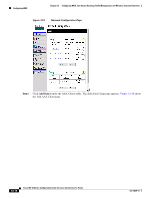 260
260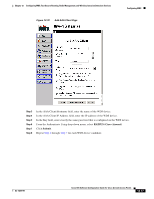 261
261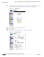 262
262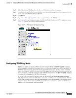 263
263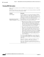 264
264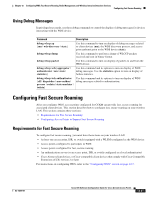 265
265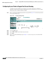 266
266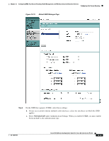 267
267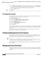 268
268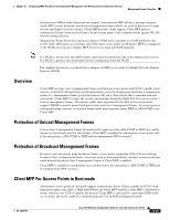 269
269 270
270