Cisco WS-C3550-24-EMI Installation Guide - Page 35
LEDs, Cisco IOS Desktop, Switching Software Configuration Guide
 |
UPC - 746320674391
View all Cisco WS-C3550-24-EMI manuals
Add to My Manuals
Save this manual to your list of manuals |
Page 35 highlights
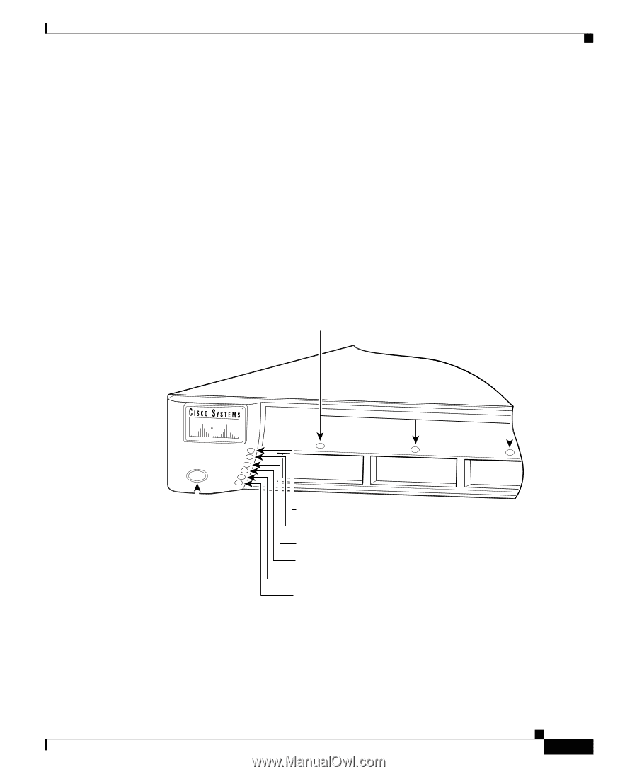
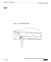
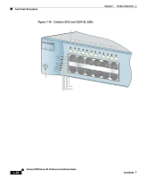
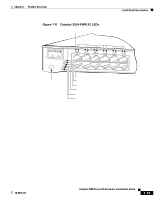
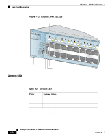
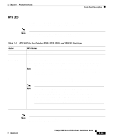
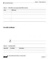
Chapter 1 Product Overview Front-Panel Description LEDs You can use the switch LEDs described in this section to monitor switch activity and its performance. Figure 1-9, Figure 1-10, Figure 1-11, and Figure 1-12 show the location of the LEDs and the Mode button that you use to select one of the port modes. All of the LEDs described in this section except the utilization meter (UTL) are visible on the VSM home page and Cluster Manager page. The Cisco IOS Desktop Switching Software Configuration Guide describes how to use the Cluster Management Suite to monitor individual switches and how to use cluster management software to monitor all the switches in a cluster. Figure 1-9 Catalyst 3508G XL LEDs GBIC module slot LEDs 18961 1 SYSTEM 2 3 RPS MODE STATUS UTIL DUPLX SPEED Mode button System LED Redundant power system LED Status LED Utilization LED Duplex LED Speed LED 78-6456-04 Catalyst 3500 Series XL Hardware Installation Guide 1-11
-
 1
1 -
2
-
3
-
4
-
5
-
6
-
7
-
8
-
9
-
10
-
11
-
12
-
13
-
14
-
15
-
16
-
17
-
18
-
19
-
20
-
21
-
22
-
23
-
24
-
25
-
26
-
27
-
28
-
29
-
 30
30 -
 31
31 -
 32
32 -
 33
33 -
 34
34 -
 35
35 -
 36
36 -
 37
37 -
 38
38 -
 39
39 -
 40
40 -
41
-
42
-
43
-
44
-
45
-
46
-
47
-
48
-
49
-
50
-
51
-
52
-
53
-
54
-
55
-
56
-
57
-
58
-
59
-
60
-
61
-
62
-
63
-
64
-
65
-
66
-
67
-
68
-
69
-
70
-
71
-
72
-
73
-
74
-
75
-
76
-
77
-
78
-
79
-
80
-
81
-
82
-
83
-
84
-
85
-
86
-
87
-
88
-
89
-
90
-
91
-
92
-
93
-
94
-
95
-
96
-
97
-
98
-
99
-
100
-
101
-
102
-
103
-
104
-
105
-
106
-
107
-
108
-
109
-
110
-
111
-
112
-
113
-
114
-
115
-
116
-
117
-
118
-
119
-
120
-
121
-
122
-
123
-
124
-
125
-
126
-
127
-
128
-
129
-
130
-
131
-
132
-
133
-
134
-
135
-
136
-
137
-
138
-
139
-
140
-
141
-
142
-
143
-
144
-
145
-
146
-
147
-
148
-
149
-
150
-
151
-
152
-
153
-
154
-
155
-
156
-
157
-
158
-
159
-
160
 |
 |