Cisco WS-C3750X-48P-L Hardware Installation Guide - Page 70
Powering On the Switch and Running POST, STACK 1
 |
View all Cisco WS-C3750X-48P-L manuals
Add to My Manuals
Save this manual to your list of manuals |
Page 70 highlights
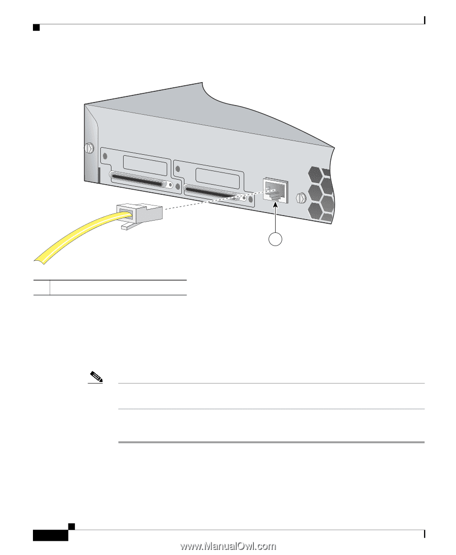
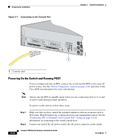
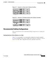
Preparing for Installation Figure 3-1 Connecting to the Console Port Chapter 3 Switch Installation STACK 1 STACK 2 CONSOLE 86685 1 1 Console port Powering On the Switch and Running POST If your configuration has an RPS, connect the switch and the RPS to the same AC power source. See the "Power Connectors" section on page 2-16, and refer to the Cisco RPS documentation for more information. 3-10 Note Always put the RPS in standby mode when you are connecting devices to it and in active mode during normal operation. To power on the switch, follow these steps: Step 1 Step 2 Make sure that you have started the terminal emulation software program (such as ProComm, HyperTerminal, tip, or minicom) from your management station. See the "Connecting a PC or Terminal to the Console Port" section on page 3-8 for information on connecting to the switch console port. Connect one end of the AC power cord to the AC power connector on the switch. Catalyst 3750 Switch Hardware Installation Guide 78-15136-02
-
 1
1 -
2
-
3
-
4
-
5
-
6
-
7
-
8
-
9
-
10
-
11
-
12
-
13
-
14
-
15
-
16
-
17
-
18
-
19
-
20
-
21
-
22
-
23
-
24
-
25
-
26
-
27
-
28
-
29
-
30
-
31
-
32
-
33
-
34
-
35
-
36
-
37
-
38
-
39
-
40
-
41
-
42
-
43
-
44
-
45
-
46
-
47
-
48
-
49
-
50
-
51
-
52
-
53
-
54
-
55
-
56
-
57
-
58
-
59
-
60
-
61
-
62
-
63
-
64
-
 65
65 -
 66
66 -
 67
67 -
 68
68 -
 69
69 -
 70
70 -
 71
71 -
 72
72 -
 73
73 -
 74
74 -
 75
75 -
76
-
77
-
78
-
79
-
80
-
81
-
82
-
83
-
84
-
85
-
86
-
87
-
88
-
89
-
90
-
91
-
92
-
93
-
94
-
95
-
96
-
97
-
98
-
99
-
100
-
101
-
102
-
103
-
104
-
105
-
106
-
107
-
108
-
109
-
110
-
111
-
112
-
113
-
114
-
115
-
116
-
117
-
118
-
119
-
120
-
121
-
122
-
123
-
124
-
125
-
126
-
127
-
128
-
129
-
130
-
131
-
132
-
133
-
134
-
135
-
136
-
137
-
138
-
139
-
140
-
141
-
142
-
143
-
144
-
145
-
146
-
147
-
148
-
149
-
150
-
151
-
152
-
153
-
154
-
155
-
156
-
157
-
158
-
159
-
160
-
161
-
162
-
163
-
164
-
165
-
166
-
167
-
168
-
169
-
170
-
171
-
172
-
173
-
174
-
175
-
176
-
177
-
178
-
179
-
180
-
181
-
182
-
183
-
184
-
185
-
186
-
187
-
188
-
189
-
190
-
191
-
192
-
193
-
194
-
195
-
196
-
197
-
198
 |
 |