Coby TFDVD2274 Instruction Manual - Page 9
Unit View - - 22 lcd tv
 |
UPC - 716829932247
View all Coby TFDVD2274 manuals
Add to My Manuals
Save this manual to your list of manuals |
Page 9 highlights
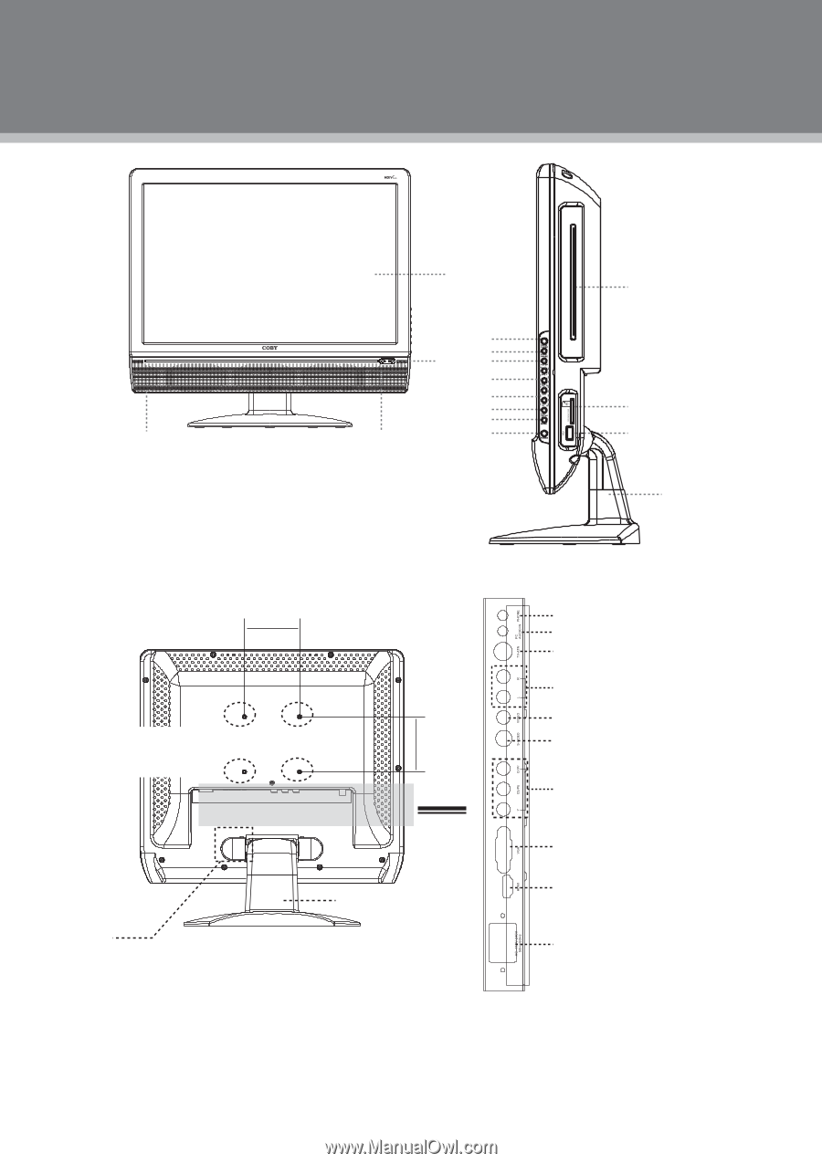
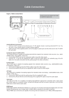
Unit View 1 4 1. TFT SCREEN 2. REMOTE SENSOR 3. POWER INDICATOR 4. SPEAKER 5. DISC SLOT 6. OPEN/CLOSE 7. PLAY/PAUSE 8. STOP 6 2 7 8 9 10 11 12 3 13 9. VOL+/10. CH+/11. LCD SETUP 12. MODE 13. POWER 14. MMC/SD/MS CARD SLOT 15. USB PORT 16. UNIT STAND 100mm < > > VESA Standard mounting thread x 4 < 100mm > Plastic part x 2 Unit Stand (e.g. TFDVD1973 Rear Cabinet) 5 14 15 16 17. PHONE JACK 18. PC AUDIO IN 19. TV ANTENNA 20. AUDIO IN((R/L) 21. VIDEO IN 22. S-VIDEO IN 23. COMPONENT IN 24. VGA IN 25. HDMI 26. POWER JACK Wall Mounting •• Pinch the edge of the plastic part and remove it from its fixture. Release the screws inside, take off the unit stand. •• Use the VESA standard mountings to fix the unit on the wall. Take care when mounting, it may cause damage or serious injury should it fall from its mountings. See the Specification page for VESA information. 3
-
 1
1 -
2
-
3
-
 4
4 -
 5
5 -
 6
6 -
 7
7 -
 8
8 -
 9
9 -
 10
10 -
 11
11 -
 12
12 -
 13
13 -
 14
14 -
15
-
16
-
17
-
18
-
19
-
20
-
21
-
22
-
23
-
24
-
25
-
26
-
27
-
28
-
29
 |
 |