Coby TFDVD2697 Instruction Manual - Page 14
Cable Connections - dvd player
 |
UPC - 716829942673
View all Coby TFDVD2697 manuals
Add to My Manuals
Save this manual to your list of manuals |
Page 14 highlights
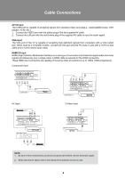
Cable Connections Figure. Cable connections Set the unit into the relative input/output mode to enable the signal pass. > Amplifier or Digital Decoder > External AV Source NOTE: We supply one set of AV cable and one piece of power cord with this product. The white/red plug of the AV cable is for the audio connection and the yellow plug for the video connection. The white/red plug of the AV cable can also be used separately to input the audio signal in the S-video/Component connection. Antenna/Power Connection 111 Connect TV RF sources to the antenna port. TV RF signals include: receiving antenna/CATV net. You can use 75 Ohm coaxial cable to connect outdoor antenna. 222 Insert one end of the supplied power cord to the player's power jack and the other end to the 110-240V AC wall outlet. Compoent Input1/2 (Y Cb/Pb Cr/Pr) The component port is capable of accepting high-definition signals from standard video sources. (e.g., cable/ satellite boxes, DVD players, VCRs, etc.) 111 Connect the Y/Pb/Pr port by the component cable to input the video signal. 222 Connect "R" "L" port by the supplied AV cable to input the audio signal. The red/white plug of the AV cable is for the audio conneciton and the yellow plug for the video connection. S-Video Input The S-Video port is capable of accepting signals from standard video sources. (e.g., cable/satellite boxes, DVD players, VCRs, etc.) 111 Connect the S-Video port by the S-Video cable to input the video signal. 222 Connect the AUDIO-L/R port by the supplied AV cable to input the audio signal. 8
-
 1
1 -
2
-
3
-
4
-
5
-
6
-
7
-
8
-
 9
9 -
 10
10 -
 11
11 -
 12
12 -
 13
13 -
 14
14 -
 15
15 -
 16
16 -
 17
17 -
 18
18 -
 19
19 -
20
-
21
-
22
-
23
-
24
-
25
-
26
-
27
-
28
-
29
 |
 |
