Compaq 100S Compaq Armada 100S and Notebook 100 Series Maintenance and Service
Compaq 100S - Armada - K6-2+ 533 MHz Manual
 |
View all Compaq 100S manuals
Add to My Manuals
Save this manual to your list of manuals |
Compaq 100S manual content summary:
- Compaq 100S | Compaq Armada 100S and Notebook 100 Series Maintenance and Service - Page 1
Compaq Armada 100S and Notebook 100 Series Maintenance and Service Guide - Compaq 100S | Compaq Armada 100S and Notebook 100 Series Maintenance and Service - Page 2
constituting a further or additional warranty. MAINTENANCE AND SERVICE GUIDE Compaq Armada 100S and Notebook 100 Series Second Edition (September 2000) First Edition (March 2000) Published in the U.S.A., U.K., Singapore, and Taiwan. Documentation Part Number 177845-002 Spare Part Number 190369-001 - Compaq 100S | Compaq Armada 100S and Notebook 100 Series Maintenance and Service - Page 3
Memory Options 1-5 1.3 Power Management Functions 1-6 1.4 Setup Configuration Utility (SCU 1-7 1.5 Compaq Configuration Record Utility 1-17 1.6 Information Gathering 1-18 1.7 Diagnostics 1-20 1.8 Design Overview 1-21 1.9 Computer External Components 1-22 chapter2 TROUBLESHOOTING 2.1 Service - Compaq 100S | Compaq Armada 100S and Notebook 100 Series Maintenance and Service - Page 4
Plastics Kit 3-6 3.4 Hardware Kit Components 3-7 3.5 Cable Kit Components 3-8 3.6 Mass Storage Devices 3-9 3.7 Miscellaneous 3-10 chapter4 REMOVAL AND REPLACEMENT PRELIMINARIES 4.1 Required Tools 4-1 4.2 Service Considerations 4-1 4.3 Removable Drive Damage Prevention 4-2 4.4 Electrostatic - Compaq 100S | Compaq Armada 100S and Notebook 100 Series Maintenance and Service - Page 5
5.11 Hard Drive 5-18 5.12 Real Time Clock (RTC) Battery 5-19 5.13 Keyboard 5-20 5.14 EMI Shield 5-22 5.15 TouchPad 5-24 5.16 Speakers 5-25 5.17 Display Assembly 5-26 5.18 Speaker Housing 5-31 5.19 System Board 5-33 5.20 Diskette Drive 5-37 appendix A CONNECTOR PIN ASSIGNMENTS A-1 appendix - Compaq 100S | Compaq Armada 100S and Notebook 100 Series Maintenance and Service - Page 6
GUIDE This Maintenance and Service Guide is a troubleshooting reference that can be used when servicing the Compaq Armada 100S and Notebook 100 Series. Compaq Computer Corporation reserves the right to make changes to the Compaq Armada 100S and Notebook 100 Series or specific instructions. NOTE - Compaq 100S | Compaq Armada 100S and Notebook 100 Series Maintenance and Service - Page 7
located on the bottom of the computer. Locating Additional Information The following documentation provides additional information about the computer: s Compaq Armada 100S and Notebook 100 Series documentation set s Microsoft Operating System Manual s Compaq Service Training Guides s Compaq Service - Compaq 100S | Compaq Armada 100S and Notebook 100 Series Maintenance and Service - Page 8
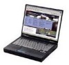
-MHz processors, 13.3-inch SVGA TFT and 12.1-inch SVGA TFT or HPA displays, a 5.0-GB hard drive, and a 24X Max CD-ROM drive. The computer also comes equipped with a TouchPad pointing device and 4 MB of shared UMA memory. Figure 1-1. Compaq Armada 100S and Notebook 100 Series Product Description 1-1 - Compaq 100S | Compaq Armada 100S and Notebook 100 Series Maintenance and Service - Page 9
CTFT, SVGA HPA, SVGA 5 Hard drive size 5 = 5.0 GB (GB) 6 Integrated M = Modem communication 0 = None 7 RAM (in MB) 64 = 64 MB 32 = 32 MB 8 Operating system 98 = Microsoft Windows 98 SB = Microsoft Small Business 2 = Microsoft Word 2000 P = Personal 1 The Compaq Armada 100S uses an AMD K6 - Compaq 100S | Compaq Armada 100S and Notebook 100 Series Maintenance and Service - Page 10
Compaq Armada 100S and Notebook 100 98/P 200516-XX4 FQ63 M 64 98/2 200525-XX4 FQ51 M 64 98 200515-XX4 FQ52 M 64 98 200515-XX5 FQ52 0 64 98/2 200520-XX4 FQ53 M 64 98/SB 200522-XX4 FQ54 M 32 98/2 200514-XX4 FQ41 M 32 98 200517-XX4 FQ42 M 32 98 200517-XX5 FQ42 0 32 98/2 200519-XX4 FQ43 M 32 98 - Compaq 100S | Compaq Armada 100S and Notebook 100 Series Maintenance and Service - Page 11
, expandable to 160 MB, varying by computer model. The Compaq Armada 100S and Notebook 100 also feature a SODIMM memory expansion slot, capable of accepting a memory expansion board of 32-, 64-, or 128-MB. s Primary memory cache is 64 KB; secondary memory cache is 512 KB. s 13.3-inch SVGA TFT or - Compaq 100S | Compaq Armada 100S and Notebook 100 Series Maintenance and Service - Page 12
s One Type II PC Card slot with support for both 32-bit CardBus and 16-bit PC Cards. s Mass storage devices include a 5.0-GB hard drive; 3.5-inch, 1.44-MB diskette drive; and 24X Max CD-ROM drive. s Connectors for parallel, serial, audio in/out, external monitor, universal serial bus, external - Compaq 100S | Compaq Armada 100S and Notebook 100 Series Maintenance and Service - Page 13
be configured from the Setup Configuration Utility (SCU : s Hard disk drive s Diskette drive s CD-ROM drive s LCD RAM (Standby) or Suspend-to-Disk (Hibernation) depending on the Suspend Data To setting in the SCU program. AMD PowerNow! NOTE: This power mode is available only on the Compaq Notebook 100 - Compaq 100S | Compaq Armada 100S and Notebook 100 Series Maintenance and Service - Page 14
into memory, returning the computer to the state it was in before it was suspended. If there is no Suspend-to-Disk partition on the hard disk, use Suspend-to-RAM. 1.4 Setup Configuration Utility (SCU) The system comes with a Setup Configuration Utility (SCU). This utility configures BIOS settings - Compaq 100S | Compaq Armada 100S and Notebook 100 Series Maintenance and Service - Page 15
system settings. This section also displays submenus for items that provide multiple options. Information and navigation area-provides keyboard/mouse instructions for moving around and making decisions. You can select items using either the keyboard or the TouchPad/mouse. 1-8 Product Description - Compaq 100S | Compaq Armada 100S and Notebook 100 Series Maintenance and Service - Page 16
to boot only from that device. Diskette A Hard Drive C CD-ROM Drive Allows the creation of an administrator-level password. This controls whether a nonadministrator can boot the system or enter the SCU utility. Sets up a user-level password. This controls booting, running the SCU, or resuming the - Compaq 100S | Compaq Armada 100S and Notebook 100 Series Maintenance and Service - Page 17
setting enables or disables usage of L2 cache memory. The default setting is Enabled. NOTE: The L2 cache enable feature is available only on the Compaq Notebook 100 Personal Computer. Disks Menu The Disks menu contains settings that configure the system diskette drive and hard drive. It also sets - Compaq 100S | Compaq Armada 100S and Notebook 100 Series Maintenance and Service - Page 18
is present. A check mark indicates that the item is Enabled. An underline indicates Disabled. Sets the type of hard disk drive in the system. HDD Timing-Sets the data transmit mode of the hard drive. The default is Ultra DMA-33. I/O 32 bit Transfer-If enabled, allows for a faster transfer rate. The - Compaq 100S | Compaq Armada 100S and Notebook 100 Series Maintenance and Service - Page 19
Numlock Keyboard Repeat Components Menu Function Default Assigns COM1 and COM2 to specific functions. In general, assign COM1 to RS-232 (the serial . Sets the address for the LPT (parallel) port. This system supports Enhanced Parallel Port (EPP) and Extended Capabilities Port (ECP) standards. - Compaq 100S | Compaq Armada 100S and Notebook 100 Series Maintenance and Service - Page 20
with the exception of Suspend Controls are automatically disabled. Timeout Settings-Sets up timeout functions. Note that some operating systems such as Windows 98 have built-in APM/ACPI configurations that could override these settings. Item Video Timeout Disk Timeout Global Timeout Power Menu - Compaq 100S | Compaq Armada 100S and Notebook 100 Series Maintenance and Service - Page 21
item in the Suspend Controls submenu. Choices may be Suspend-toRAM or Suspend-to-Disk. When Suspend-to-RAM (Standby) mode RAM mode. When Suspend-to-Disk (Hibernation) mode is initiated, the system preserves all running application programs as a file in a suspend-to-disk partition on the hard disk - Compaq 100S | Compaq Armada 100S and Notebook 100 Series Maintenance and Service - Page 22
functions. Item Clock Control Mechanism Clock Run Enable Advanced CPU Controls Menu Function Sets the CPU activity under normal condition. The available options range from 6% to full speed (Disabled). Note that although this item sets the usage of CPU resources, the CPU can still reach its full - Compaq 100S | Compaq Armada 100S and Notebook 100 Series Maintenance and Service - Page 23
also restores default settings and displays BIOS version information. When troubleshooting the Compaq Armada 100S and Notebook 100, it is important to obtain all facts about the error condition. Obtain details of the problem and any circumstances surrounding the problem. Obtain all error codes or - Compaq 100S | Compaq Armada 100S and Notebook 100 Series Maintenance and Service - Page 24
of multiple sessions. The Compaq Configuration Record Utility captures data as sessions; a session is defined as an organized group of data describing the configured state of the system at a specific point in time. The session information is maintained in a log file, located in the same directory - Compaq 100S | Compaq Armada 100S and Notebook 100 Series Maintenance and Service - Page 25
different configuration snapshots (or sessions). For example, when a user requests the Configuration Record Utility to generate a comparison of all information recorded, such as changes in amounts of free memory. Reviewing the differences occurring between different configuration snapshots can - Compaq 100S | Compaq Armada 100S and Notebook 100 Series Maintenance and Service - Page 26
configuration. It provides a much greater depth of information on hardware, operating system services, and drivers that are running on the computer. The Compaq Configuration Record Utility is supported under Windows 95, Windows 98, and Windows NT 4.0. This utility is available on SoftPaq. Product - Compaq 100S | Compaq Armada 100S and Notebook 100 Series Maintenance and Service - Page 27
1.7 Diagnostics Using Compaq Diagnostics s Access Compaq Diagnostics for Windows by selecting Start!Settings!Control Panel!Compaq Diagnostics. s drive, select the File menu, then select Print or Save As. 7. To exit, select the File menu!Exit. NOTE: Compaq Diagnostics may intermittently fail the CPU - Compaq 100S | Compaq Armada 100S and Notebook 100 Series Maintenance and Service - Page 28
5 for removal and replacement procedures. The system board provides the following device connections: s Memory expansion board s Hard drive s Display s Keyboard/TouchPad s Audio s AMD K6-2+ and AMD K6-2 processor s Fan s PC Cards s Modem or modem/NIC The Compaq Armada 100S and Notebook 100 use an - Compaq 100S | Compaq Armada 100S and Notebook 100 Series Maintenance and Service - Page 29
Stereo speakers Produce high-quality stereo sound. 4 Power state lights Indicate AC/battery power and charge status. 5 Display release latch Opens the computer. 6 status. 8 Volume control Adjusts the volume of the stereo speakers. 9 CD-ROM drive Accepts CD-ROM disks. 10 Infrared port - Compaq 100S | Compaq Armada 100S and Notebook 100 Series Maintenance and Service - Page 30
modem cable to an internal modem models only) modem. 4 PC Card slot Supports 32-bit (CardBus) and 16-bit PC Cards. 5 Battery pack Accepts either the standard 9-cell NiMH or optional 8-cell Li ion battery packs. The battery pack supplies power to the computer if external power is not available - Compaq 100S | Compaq Armada 100S and Notebook 100 Series Maintenance and Service - Page 31
volume control. The internal computer speakers are turned off when external speakers or headphones are plugged into this jack. Connects USB devices, such as cameras for video conferencing, or hubs which connect multiple USB devices. The USB connector is a powered hub. When running Windows 98, any - Compaq 100S | Compaq Armada 100S and Notebook 100 Series Maintenance and Service - Page 32
Table 1-6 continued Item Component 6 External monitor connector 7 Keyboard/mouse connector 8 AC Adapter connector Function Connects an optional external monitor, overhead projector, or TV adapter. Connects an optional full-sized keyboard or a mouse. Both external mouse and computer pointing device - Compaq 100S | Compaq Armada 100S and Notebook 100 Series Maintenance and Service - Page 33
2 chapter TROUBLESHOOTING 2.1 Service Considerations When troubleshooting the Compaq Armada 100S and Notebook 100, it is important to obtain all facts about the situation. Obtain details of the problem and any circumstances surrounding the problem. Obtain all error codes or beep codes. Once all - Compaq 100S | Compaq Armada 100S and Notebook 100 Series Maintenance and Service - Page 34
BIOS runs a series of internal checks on the hardware. This allows the computer to detect problems as early as the power-on stage. The POST alerts you to problems the RAM. Start point of execution of boot loader in RAM. Shadow screen BIOS. Initialize clock synthesizer. Initialize audio controller. - Compaq 100S | Compaq Armada 100S and Notebook 100 Series Maintenance and Service - Page 35
monochrome adapter. 1Fh Test 8237A page registers. 2Oh Perform keyboard self-test. 21h Test and initialize keyboard controller. 22h Check if RAM valid. 23h Test battery fail & X-SUM. 24h Test DMA controllers. 25h Initialize 8237 controller. 26h Initialize interrupt vectors table - Compaq 100S | Compaq Armada 100S and Notebook 100 Series Maintenance and Service - Page 36
safely (2). 36h RAM test complete. 37h Protected mode exit successfully. 38h Update keyboard output port to disable gate of A20. 39h Setup cache controller. 3Ah Test if 18.2Hz periodic working. 3Bh Initialize BIOS data area at 40.0. 3Ch Initialize the hardware interrupt vector table - Compaq 100S | Compaq Armada 100S and Notebook 100 Series Maintenance and Service - Page 37
in. s Check to ensure the battery is charged. s Try another working battery or adapter. Problem Possible Cause Solution There is no display s Remove I/O devices and cables and reconnect one by one to determine which is causing the problem. Table 2-4 VGA Controller Failure Problem Possible - Compaq 100S | Compaq Armada 100S and Notebook 100 Series Maintenance and Service - Page 38
D/A BD is good. s Make sure cables are installed properly. Table 2-6 External Monitor No Display Problem The CRT monitor shows nothing or abnormal color. The picture is fine on the LCD. Possible Cause 's power cord. s Check the CRT monitor cable. s Try a working monitor. 2-6 Troubleshooting - Compaq 100S | Compaq Armada 100S and Notebook 100 Series Maintenance and Service - Page 39
. s Try another working diskette drive. CD-ROM Drive Test Error s Try another working CD. s Ensure that the CD-ROM drive is connected properly. s Try another working CD-ROM drive. Hard Drive Test Error s Check the hard disk drive settings. s Try another working hard disk drive. Troubleshooting 2-7 - Compaq 100S | Compaq Armada 100S and Notebook 100 Series Maintenance and Service - Page 40
. s Ensure that the USB driver is installed. s Verify that or other I/O devices are installed properly (including associated drivers). s Ensure that the COM port is set properly are connected properly. s Ensure that the appropriate software drivers are installed. s Try another working speaker, cable - Compaq 100S | Compaq Armada 100S and Notebook 100 Series Maintenance and Service - Page 41
CATALOG This chapter provides an illustrated parts breakdown and a reference for spare part numbers and option part numbers for the Compaq Armada 100S and Notebook 100 Personal Computers. 3.1 Serial Number Location When ordering parts or requesting information, provide the computer serial number - Compaq 100S | Compaq Armada 100S and Notebook 100 Series Maintenance and Service - Page 42
3.2 Computer System Major Components Figure 3-2. Computer System Major Components 3-2 Illustrated Parts Catalog - Compaq 100S | Compaq Armada 100S and Notebook 100 Series Maintenance and Service - Page 43
2b 2c 2d 2e 2f 2g 3a 3b 3c 3d 4 5 Description Spare Part Number Display assembly 13.3-inch panel, TFT (used only with config. codes beginning I/O cover Modem cover Fan/CPU cover 176048-001 Hardware Kit, includes: Speakers (2) Real time clock battery and sponge Processor bracket Modem shield - Compaq 100S | Compaq Armada 100S and Notebook 100 Series Maintenance and Service - Page 44
Computer System Major Components (continued) 3-4 Illustrated Parts Catalog - Compaq 100S | Compaq Armada 100S and Notebook 100 Series Maintenance and Service - Page 45
Description Spare Part Number 6 EMI shield 176002-001 7 TouchPad 176044-001 8 5.0-GB hard drive 176040-001 drive, 1.44-Megabyte 176047-001 Cable Kit, includes: 176004-001 11a Diskette drive cable 11b Modem cable 11c CD-ROM drive cable 12 Base assembly 176042-001 13 Battery - Compaq 100S | Compaq Armada 100S and Notebook 100 Series Maintenance and Service - Page 46
3.3 Miscellaneous Plastics Kit Figure 3-3. Miscellaneous Plastics Kit Components Table 3-2 Miscellaneous Plastics Kit Components Spare Part Number 176048-001 Item Description 1 Left and right hinge covers 2 Speaker housing 3 RJ11 cover 4 PC Card door 5 I/O cover 6 Modem cover 7 Fan/ - Compaq 100S | Compaq Armada 100S and Notebook 100 Series Maintenance and Service - Page 47
3.4 Hardware Kit Components Figure 3-4. Hardware Kit Components Table 3-3 Hardware Kit Components Spare Part Number 176049-001 Item Description 1 Speakers (2) 2 Real time clock battery 3 Processor bracket 4 Modem shield Illustrated Parts Catalog 3-7 - Compaq 100S | Compaq Armada 100S and Notebook 100 Series Maintenance and Service - Page 48
3.5 Cable Kit Components Figure 3-5. Cable Kit Components Table 3-4 Spare Parts: Cable Kit Components Spare Part Number 176004-001 Item Description 1 Diskette drive cable 2 Modem cable 3 CD-ROM drive cable 3-8 Illustrated Parts Catalog - Compaq 100S | Compaq Armada 100S and Notebook 100 Series Maintenance and Service - Page 49
3.6 Mass Storage Devices Figure 3-6. Mass Storage Devices Table 3-5 Spare Parts: Mass Storage Devices Item Description Spare Part Number 1 5.0-GB hard drive 2 24X CD-ROM drive (standard) 3 Diskette drive, 1.44-Megabyte 176040-001 176039-001 176047-001 Illustrated Parts Catalog 3-9 - Compaq 100S | Compaq Armada 100S and Notebook 100 Series Maintenance and Service - Page 50
) Description Spare Part Number AC Adapter, 50 W Automobile Adapter Compaq Armada 100S and Notebook 100 Maintenance & Service Guide Logo kit Memory expansion board 128 MB 64 MB 32 MB Miscellaneous Screw Kit PC Cards Compaq Microcom 420 56K Global Modem Compaq Netelligent 10/100 TX network - Compaq 100S | Compaq Armada 100S and Notebook 100 Series Maintenance and Service - Page 51
whole unit return." Check with your Geo Service Manager to determine if warranty repair costs are covered before ordering spare parts or performing repairs. This chapter provides essential information for proper and safe removal and replacement service. 4.1 Required Tools You will need the following - Compaq 100S | Compaq Armada 100S and Notebook 100 Series Maintenance and Service - Page 52
care; they tear easily. CAUTION: When servicing the computer, ensure that cables are placed in their proper location during the reassembly process. Improper cable placement can damage the computer. 4.3 Removable Drive Damage Prevention Removable drives are fragile components that must be handled - Compaq 100S | Compaq Armada 100S and Notebook 100 Series Maintenance and Service - Page 53
temperature extremes or to liquids. s If a drive must be mailed, do the following: place the drive into a bubble pack mailer or other suitable electrostatic-sensitive parts in their containers until they arrive at static-free workstations. s Place items on a grounded surface before removing them - Compaq 100S | Compaq Armada 100S and Notebook 100 Series Maintenance and Service - Page 54
surface and use properly grounded tools and equipment. s Use field service tools, such as cutters, screwdrivers, and vacuums that are conductive. Handle electrostatic-sensitive components, parts, and assemblies by the case or PCM laminate. Handle them only at static-free workstations. s Avoid - Compaq 100S | Compaq Armada 100S and Notebook 100 Series Maintenance and Service - Page 55
-conductive foam s Conductive tabletop workstations with ground cord of one-megohm resistance s Static-dissipative table or floor mats with hard tie to ground s Field service kits s Static awareness labels s Material-handling packages s Non-conductive plastic bags, tubes, or boxes s Metal tote boxes - Compaq 100S | Compaq Armada 100S and Notebook 100 Series Maintenance and Service - Page 56
carpet 35,000 V Walking across vinyl floor 12,000 V Motions of bench worker 6,000 V Removing DIPS from plastic tube 2,000 V Removing DIPS from vinyl tray 11,500 V Removing DIPS from Styrofoam 14,500 V Removing bubble pack from PCB 26,500 V Packing PCBs in foam-lined box 21,000 V NOTE - Compaq 100S | Compaq Armada 100S and Notebook 100 Series Maintenance and Service - Page 57
ordering spare parts or performing repairs. This chapter provides removal and replacement procedures for the Compaq Armada 100S and Notebook 100 Series. 5.1 Serial Number Report the computer serial number to Compaq when requesting information or ordering spare parts. The serial number is located on - Compaq 100S | Compaq Armada 100S and Notebook 100 Series Maintenance and Service - Page 58
5.3 Preparing the Computer for Disassembly 5.4 Battery Pack 5.5 Modem 5.6 Fan Assembly 5.7 CD-ROM Drive 5.8 Processor 5.9 Memory Removing a Memory Expansion Board Installing a Memory Expansion Board 5.10 Top Cover 5.11 Hard Drive 5.12 Real Time Clock (RTC) Battery 5.13 Keyboard 5.14 EMI Shield 5.15 - Compaq 100S | Compaq Armada 100S and Notebook 100 Series Maintenance and Service - Page 59
5-2). 4. Slide the battery release switch to the left —. 5. Lift up the front edge of the battery pack and swing it away from computer ˜. 6. Remove the battery pack. Figure 5-2. Removing the Battery Pack Reverse the removal procedure to replace the battery pack. Removal and Replacement Procedures - Compaq 100S | Compaq Armada 100S and Notebook 100 Series Maintenance and Service - Page 60
Plastics Kit) Modem shield (spared in Hardware Kit) Modem cable (spared in Cable Kit) 176052-001 176048-001 176046-001 176004-001 1. Prepare the computer for disassembly (Section 5.3). 2. Turn the computer bottom side up with the front facing forward. 3. Remove the screw – securing the modem cover - Compaq 100S | Compaq Armada 100S and Notebook 100 Series Maintenance and Service - Page 61
6. Remove the two screws – securing the modem shield to the base assembly (Figure 5-4). 7. Remove the modem shield —. Figure 5-4. Removing the Modem Shield Removal and Replacement Procedures 5-5 - Compaq 100S | Compaq Armada 100S and Notebook 100 Series Maintenance and Service - Page 62
board to disconnect it from the system board ˜. 11. If necessary, disconnect the modem cable from the modem board and replace the modem cable ™. Figure 5-5. Removing the Modem 12. Remove the modem board. Reverse the removal procedure to replace the modem - Compaq 100S | Compaq Armada 100S and Notebook 100 Series Maintenance and Service - Page 63
computer for disassembly (Section 5.3). 2. Turn the computer bottom side up with the front facing forward. 3. Remove the four screws securing the fan/CPU cover to the base assembly. Note that the two screws removed from the back edge of the cover – differ in size from the other two screws — (Figure - Compaq 100S | Compaq Armada 100S and Notebook 100 Series Maintenance and Service - Page 64
the fan cable – from the system board (Figure 5-7). 6. Remove the four screws — securing the fan assembly to the system board. 7. Remove the fan assembly ˜. Figure 5-7. Removing the Fan Assembly Reverse the removal procedure to replace the fan assembly. 5-8 Removal and Replacement Procedures - Compaq 100S | Compaq Armada 100S and Notebook 100 Series Maintenance and Service - Page 65
the CD-ROM drive cable from the system board – (Figure 5-8). 4. Remove the screw securing the CD-ROM drive to the base assembly —. 5. Push on the back of the CD-ROM drive and slide the drive to the left ˜. Figure 5-8. Removing the CD-ROM Drive 6. Remove the CD-ROM drive. Removal and Replacement - Compaq 100S | Compaq Armada 100S and Notebook 100 Series Maintenance and Service - Page 66
7. If necessary, disconnect the CD-ROM drive cable from the CD-ROM drive (Figure 5-9). Figure 5-9. Removing the CD-ROM Drive Cable Reverse the removal procedure to replace the CD-ROM drive. 5-10 Removal and Replacement Procedures - Compaq 100S | Compaq Armada 100S and Notebook 100 Series Maintenance and Service - Page 67
-MHz processor (used only with config. codes beginning with "FF") Processor bracket 203099-001 176036-001 176046-001 1. Prepare the computer for disassembly (Section 5.3). 2. Remove the fan assembly (Section 5.6). 3. Swing the left side of the processor bracket up and to the right – (Figure 5-10 - Compaq 100S | Compaq Armada 100S and Notebook 100 Series Maintenance and Service - Page 68
5. Insert the tip of a flat-blade screwdriver into the left socket –. This socket is marked "SKT OPEN" (Figure 5-11). 6. Swing the screwdriver to the right to release the processor —. 7. Remove the processor. Figure 5-11. Removing the Processor 5-12 Removal and Replacement Procedures - Compaq 100S | Compaq Armada 100S and Notebook 100 Series Maintenance and Service - Page 69
, make sure the white square is in the upper-right corner –. Insert the tip of the screwdriver into the right socket (marked "SKT CLOSE") — and swing the screwdriver to the right to seat the processor ˜ (Figure 5-12). Figure 5-12. Replacing the Processor Removal and Replacement Procedures 5-13 - Compaq 100S | Compaq Armada 100S and Notebook 100 Series Maintenance and Service - Page 70
Memory Memory Expansion Board Spare Part Numbers 128 MB memory expansion board 64 MB memory expansion board 32 MB memory expansion board 179966-001 179965-001 179964-001 The Compaq Armada 100S and Notebook 100 computers feature one memory expansion slot, located under the fan assembly. Removing - Compaq 100S | Compaq Armada 100S and Notebook 100 Series Maintenance and Service - Page 71
expansion boards are asymmetrically keyed (notched) to ensure correct positioning. 1. Insert the memory expansion board into an empty memory expansion slot at a 45-degree angle – (Figure 5-14). 2. Push the memory expansion board down — until the board is seated in the plastic retention clips. Figure - Compaq 100S | Compaq Armada 100S and Notebook 100 Series Maintenance and Service - Page 72
computer for disassembly (Section 5.3). 2. Turn the computer bottom side up, with the front facing forward. 3. Remove the six screws securing the top cover to the base assembly (Figure 5-15). Figure 5-15. Removing the Top Cover Screws 4. Turn the computer top side up, with the front facing forward - Compaq 100S | Compaq Armada 100S and Notebook 100 Series Maintenance and Service - Page 73
6. Lift up the front edge of the top cover – and swing it toward the back of the computer — (Figure 5-16). Figure 5-16. Removing the Top Cover 7. Remove the top cover. IMPORTANT: When installing the top cover, align the five tabs on the back edge of the top cover with the slots in - Compaq 100S | Compaq Armada 100S and Notebook 100 Series Maintenance and Service - Page 74
11 Hard Drive 5.0 GB hard drive Hard Drive Spare Part Numbers 176040-001 1. Prepare the computer for disassembly (Section 5.3). 2. Remove the top cover (Section 5.10). 3. Remove the two screws securing the hard drive to the base assembly – (Figure 5-17). 4. Lift up the right side of the hard drive - Compaq 100S | Compaq Armada 100S and Notebook 100 Series Maintenance and Service - Page 75
5.12 Real Time Clock (RTC) Battery NOTE: Removal of the RTC battery clears all information from CMOS. Real Time Clock Battery Spare Part Numbers Real time clock battery (spared in Hardware Kit) 176049-001 1. Prepare the computer for disassembly (Section 5.3). 2. Remove the top cover (Section 5.10). - Compaq 100S | Compaq Armada 100S and Notebook 100 Series Maintenance and Service - Page 76
5.13 Keyboard Keyboard Arabic Belgian Brazilian Danish French German Hungarian International Italian Japanese Keyboard Spare Part Numbers -171 -181 -201 -081 -051 -041 -211 -002 -061 -291 176041-XXX Korean -AD1 Latin American Spanish -161 Norwegian -091 Portuguese -131 Spanish -071 - Compaq 100S | Compaq Armada 100S and Notebook 100 Series Maintenance and Service - Page 77
keyboard cable is attached —. 5. Disconnect the keyboard cable from the system board ˜. Figure 5-19. Releasing the Keyboard and Disconnecting the Keyboard Cable 6. Remove the keyboard. IMPORTANT: When installing the keyboard, align the three tabs on the back edge of the keyboard with the slots in - Compaq 100S | Compaq Armada 100S and Notebook 100 Series Maintenance and Service - Page 78
5-20). NOTE: Three different sizes of screws are removed in this step: the silver screws are removed/installed in location –; the longer black screws are removed/installed in location —; the shorter black screw is removed/installed in location ˜. Also note that one of the silver screws ™ secures - Compaq 100S | Compaq Armada 100S and Notebook 100 Series Maintenance and Service - Page 79
5. Lift up the front edge of the shield and swing it toward the back of computer (Figure 5-21). Figure 5-21. Removing the EMI shield 6. Remove the EMI shield. Reverse the removal procedure to replace the EMI shield. Removal and Replacement Procedures 5-23 - Compaq 100S | Compaq Armada 100S and Notebook 100 Series Maintenance and Service - Page 80
Numbers 176044-001 1. Prepare the computer for disassembly (Section 5.3) and, in the order below, remove the following components: s Top cover (Section 5.10) s Hard drive (Section 5.11) s RTC battery (Section 5.12) s Keyboard (Section 5.13) s EMI shield (Section 5.14) 2. Lift the back edge of the - Compaq 100S | Compaq Armada 100S and Notebook 100 Series Maintenance and Service - Page 81
5.16 Speakers Speakers Spare Part Numbers Speakers (2; spared in Hardware Kit) 176049-001 1. Prepare the computer for disassembly (Section 5.3) and, in the order below, remove the following components: s Top cover (Section 5.10) s Keyboard (Section 5.13) s EMI shield (Section 5.14) 2. Disconnect - Compaq 100S | Compaq Armada 100S and Notebook 100 Series Maintenance and Service - Page 82
176037-001 222715-001, 212897-001, and 176038-001 176048-001 1. Prepare the computer for disassembly (Section 5.3) and, in the order below, remove the following components: s Top cover (Section 5.10) s Keyboard (Section 5.13) s EMI shield (Section 5.14) 2. Use a flat blade screwdriver to gently pry - Compaq 100S | Compaq Armada 100S and Notebook 100 Series Maintenance and Service - Page 83
3. Open the computer as far as it will open. 4. Disconnect the display video cable –, display inverter cable —, and microphone cable ˜ (Figure 5-25). Figure 5-25. Disconnecting the Display Cables Removal and Replacement Procedures 5-27 - Compaq 100S | Compaq Armada 100S and Notebook 100 Series Maintenance and Service - Page 84
the four screws – securing the display hinges to the base assembly (Figure 5-26). 6. Remove the display assembly —. NOTE: Make sure the display assembly is supported and does not fall when the screws are removed. Figure 5-26. Removing the Display Assembly 5-28 Removal and Replacement Procedures - Compaq 100S | Compaq Armada 100S and Notebook 100 Series Maintenance and Service - Page 85
When installing the display assembly, make sure the display video cable – is routed behind the left speaker connector — on the system board (Figure 5-27). Figure 5-27. Routing the Display Video Cable Removal and Replacement Procedures 5-29 - Compaq 100S | Compaq Armada 100S and Notebook 100 Series Maintenance and Service - Page 86
be set correctly. To set the display DIP switches on the system board, follow these steps: 1. Locate the part number label on the display microphone cable – (Figure 5-28). 2. Part numbers 541566850001/176038-001, 541566931001/ 212897-001, and 413000020183/222715-001 correspond to the 12.1-inch, TFT - Compaq 100S | Compaq Armada 100S and Notebook 100 Series Maintenance and Service - Page 87
the computer for disassembly (Section 5.3) and, in the order below, remove the following components: s Top cover (Section 5.10) s Keyboard ( Section 5.17) 2. Position the computer so the rear panel faces forward. 3. Remove the screw securing the I/O cover to the speaker housing – (Figure 5-29). - Compaq 100S | Compaq Armada 100S and Notebook 100 Series Maintenance and Service - Page 88
6. Remove the five screws securing the speaker housing to the base assembly – (Figure 5-30). 7. Remove the speaker housing —. Figure 5-30. Removing the Speaker Housing Reverse the removal procedure to replace the speaker housing. 5-32 Removal and Replacement Procedures - Compaq 100S | Compaq Armada 100S and Notebook 100 Series Maintenance and Service - Page 89
DIP switches. 1. Prepare the computer for disassembly (Section 5.3) and, in the order below, remove the following components: s Top cover (Section 5.10) s Hard drive (Section 5.11) s RTC battery (Section 5.12) s Keyboard (Section 5.13) s EMI shield (Section 5.14) s TouchPad (Section 5.15) s Speakers - Compaq 100S | Compaq Armada 100S and Notebook 100 Series Maintenance and Service - Page 90
3. Remove the two screws securing the system board to the base assembly (Figure 5-31). Figure 5-31. Removing the System Board Screws 4. Turn the computer top side up with the front facing forward. 5-34 Removal and Replacement Procedures - Compaq 100S | Compaq Armada 100S and Notebook 100 Series Maintenance and Service - Page 91
cover from the left side of the computer – (Figure 5-32). 6. Disconnect the diskette drive LIF (low insertion force) cable from the system board —. 7. Remove the system board from the base assembly ˜. Figure 5-32. Removing the System Board IMPORTANT: When installing the system board, make sure the - Compaq 100S | Compaq Armada 100S and Notebook 100 Series Maintenance and Service - Page 92
If necessary, remove the PC Card door by partially opening the door –, flexing the middle of the door away from the computer —, and removing the door (Figure 5-33). Figure 5-33. Removing the PC Card Door 5-36 Removal and Replacement Procedures - Compaq 100S | Compaq Armada 100S and Notebook 100 Series Maintenance and Service - Page 93
176004-001 1. Prepare the computer for disassembly (Section 5.3) and, in the order below, remove the following components: s Top cover (Section 5.10) s Hard drive (Section 5.11) s RTC battery (Section 5.12) s Keyboard (Section 5.13) s EMI shield (Section 5.14) s TouchPad (Section 5.15) s Speakers - Compaq 100S | Compaq Armada 100S and Notebook 100 Series Maintenance and Service - Page 94
2. Lift the back edge of the diskette drive – and swing it up and toward the front of the base assembly — (Figure 5-34). Figure 5-34. Removing the Diskette Drive 3. Remove the diskette drive. 5-38 Removal and Replacement Procedures - Compaq 100S | Compaq Armada 100S and Notebook 100 Series Maintenance and Service - Page 95
If necessary, remove the diskette drive cable by releasing the ZIF connector – to which the cable is attached and disconnecting the cable — (Figure 5-35). Figure 5-35. Disconnecting the Diskette Drive Cable Removal and Replacement Procedures 5-39 - Compaq 100S | Compaq Armada 100S and Notebook 100 Series Maintenance and Service - Page 96
of the drive through the opening in the base assembly –, then lower the back edge of the drive into the base assembly —. Make sure the FPC cable ˜ on the back of the drive fits inside the diskette drive shield (Figure 5-36). Figure 5-36. Installing the Diskette Drive 5-40 Removal and Replacement - Compaq 100S | Compaq Armada 100S and Notebook 100 Series Maintenance and Service - Page 97
A appendix CONNECTOR PIN ASSIGNMENTS Connector 13 5 7 2468 Table A-1 RJ-11 Pin Signal 1 NC_J3A 2 NC_J3B 3 TIP 4 RING 5 NC_J3C 6 NC_J3D 7 Unused 8 Unused Table A-2 Serial Connector 1 23 45 6789 Pin Signal 1 Carrier detect 2 Receive data 3 Transmit data 4 Data terminal - Compaq 100S | Compaq Armada 100S and Notebook 100 Series Maintenance and Service - Page 98
Connector 12 Table A-3 Microphone Jack Pin Signal 1 Audio in 2 Ground Connector 12 Table A-4 Stereo Speaker/Headphone Jack Pin Signal 1 Audio out 2 Ground Connector 12 Table A-5 Stereo Line-in Jack Pin Signal 1 Audio in 2 Ground A-2 Connector Pin Assignments - Compaq 100S | Compaq Armada 100S and Notebook 100 Series Maintenance and Service - Page 99
Table A-6 Parallel Connector 13 12 11 10 9 8 7 6 5 4 3 2 1 25 24 23 22 21 20 19 18 17 16 15 14 Pin Signal 1 Strobe 2 Data bit 0 3 Data bit 1 4 Data bit 2 5 Data bit 3 6 Data bit 4 7 Data bit 5 8 Data bit 6 9 Data bit 7 10 Acknowledge 11 Busy 12 Paper end 13 Select Pin Signal 14 Auto linefeed 15 - Compaq 100S | Compaq Armada 100S and Notebook 100 Series Maintenance and Service - Page 100
30 60 90 120 Pin Signal 1 EBOXL 2 AGND 3 EBOXS1 4 RED 5 AGND 6 GREEN 7 AGRD 8 BLUE 9 AGND 10 VSYNC 11 HSYNC 12 DDC DAT 13 DDC CLK 14 GND 15 INDEX 16 RDATA 17 TRK0 18 WDATA 19 WGATE 20 STEP 21 DIR 22 POWER on 23 SYS reset 24 GND 25 DSKCHG 26 +5 V (VDD) 27 AUGND 28 XA2/L in Table A-7 Docking - Compaq 100S | Compaq Armada 100S and Notebook 100 Series Maintenance and Service - Page 101
SERIRQ 93 PS2 CLK 94 EXPREQ 95 AD[29] 96 AD[31] 97 AD[30] 98 AD[28] 99 AD[26] 100 GND 101 AD[24] 102 AD[22] 103 AD[20] 104 AD[18] 105 AD[16] 106 GND 107 AD[15] 108 AD[13] 109 AD[11] 110 AD[09] 111 GND 112 AD[06] 113 AD[04] 114 AD[02] 115 AD[00 - Compaq 100S | Compaq Armada 100S and Notebook 100 Series Maintenance and Service - Page 102
Table A-7 continued Pin Signal 125 RSVD1/M CTRL2 126 XSC/L OUT SN 127 RSVD2/M OFF HOOK 128 KB DATA 129 MGND 130 STANDBY 131 M DRZP 132 M DRXN 133 VBATT 134 EXPGNT 135 VBATT 136 GND 137 VBATT 138 PS2 DATA 139 VBATT 140 AD[25] 141 VBATT 142 AD[27] 143 VBATT 144 AD[23] 145 GND 146 AD[21] 147 AD[19] 148 - Compaq 100S | Compaq Armada 100S and Notebook 100 Series Maintenance and Service - Page 103
Connector 6 5 4 KEY 3 21 Table A-8 External Keyboard/Mouse Connector Pin Signal 1 Keyboard/mouse data 2 Keyboard/mouse data 3 Ground 4 +5 VDC 5 Keyboard/mouse CLK 6 Keyboard/mouse CLK Table A-9 External Monitor Connector 5 43 21 10 KEY 8 7 6 15 14 13 12 11 Pin Signal 1 Red - Compaq 100S | Compaq Armada 100S and Notebook 100 Series Maintenance and Service - Page 104
feature of the Compaq Armada 100S and Notebook 100 Personal Computers permit them to operate from any line voltage from 100 to 120 volts service provider. General Requirements The requirements listed below are applicable to all countries: 1. The length of the power cord set must be at least 5.00 - Compaq 100S | Compaq Armada 100S and Notebook 100 Series Maintenance and Service - Page 105
Country-Specific Requirements 3-Conductor Power Cord Set Requirements-By Country Country Accredited Agency Applicable Note Numbers Australia EANSW 1 Austria OVE 1 Belgium CEBC 1 Canada CSA 2 Denmark DEMKO 1 Finland - Compaq 100S | Compaq Armada 100S and Notebook 100 Series Maintenance and Service - Page 106
ROM drive cable disconnecting, 5-9, 5-10 illustrated, 3-2, 3-8 illustrated, 1-22, 3-2, 3-9 removing, 5-9 spare part number, 3-5, 3-9, 5-9 checklist, troubleshooting, 2-1 Compaq configuration record utility, 1-17 Compaq Microcom 420 56K PC Card modem, spare part number, 3-10 Compaq Netelligent 10/100 - Compaq 100S | Compaq Armada 100S and Notebook 100 Series Maintenance and Service - Page 107
illustrated, 3-2 removing, 5-8 spare part number, 3-5, 5-7 fan/CPU cover illustrated, 3-2, 3-6 removing, 5-7 features, 1-4 floppy disk drive. See diskette drive G grounding procedures, 4-4 H hard drive illustrated, 3-2, 3-9 removing, 5-18 spare part number, 3-5, 3-9, 5-18 Hardware Kit components - Compaq 100S | Compaq Armada 100S and Notebook 100 Series Maintenance and Service - Page 108
cable, illustrated, 3-8 cover illustrated, 3-2, 3-6 removing, 5-4 illustrated, 3-2 removing, 5-6 shield illustrated, 3-2, 3-7 removing, 5-5 spare part number, 3-5, 5-4 modem/network interface card combination, 3-10 PC Card Compaq Microcom 500 10/100 +56K spare part number, 3-10 monitor connector - Compaq 100S | Compaq Armada 100S and Notebook 100 Series Maintenance and Service - Page 109
RJ-11 jack, pinout, A-1 RTC battery illustrated, 3-2, 3-7 removing, 5-19 S SCU main screen, 1-8 starting, 1-7 security cable slot illustrated, 1-23 serial connector illustrated, 1-24 pinout, A-1 serial number, x location, 3-1, 5-1 service consideration, 2-1, 4-1 setup configuration utility, 1-7 Show - Compaq 100S | Compaq Armada 100S and Notebook 100 Series Maintenance and Service - Page 110
line-in jack, pinout, A-2 speaker jack, pinout, A-2 Suspend Controls menu, 1-15 Suspend-to-Disk, 1-7 Suspend-to-RAM, 1-7 system board 32 MB spare part number, 3-5 64 MB spare part number, 3-5 illustrated, 3-2 removing, 5-35 system board, 32 MBRAM spare part number, 5-33 system board, 64 MB spare
-
 1
1 -
 2
2 -
 3
3 -
 4
4 -
 5
5 -
 6
6 -
 7
7 -
8
-
9
-
10
-
11
-
12
-
13
-
14
-
15
-
16
-
17
-
18
-
19
-
20
-
21
-
22
-
23
-
24
-
25
-
26
-
27
-
28
-
29
-
30
-
31
-
32
-
33
-
34
-
35
-
36
-
37
-
38
-
39
-
40
-
41
-
42
-
43
-
44
-
45
-
46
-
47
-
48
-
49
-
50
-
51
-
52
-
53
-
54
-
55
-
56
-
57
-
58
-
59
-
60
-
61
-
62
-
63
-
64
-
65
-
66
-
67
-
68
-
69
-
70
-
71
-
72
-
73
-
74
-
75
-
76
-
77
-
78
-
79
-
80
-
81
-
82
-
83
-
84
-
85
-
86
-
87
-
88
-
89
-
90
-
91
-
92
-
93
-
94
-
95
-
96
-
97
-
98
-
99
-
100
-
101
-
102
-
103
-
104
-
105
-
106
-
107
-
108
-
109
-
110
 |
 |

Compaq Armada 100S and
Notebook 100 Series
Maintenance and Service Guide