Compaq 15-f100 Maintenance and Service Guide - Page 46
Solid-state drive, Remove the battery see
 |
View all Compaq 15-f100 manuals
Add to My Manuals
Save this manual to your list of manuals |
Page 46 highlights
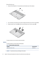
5. If the WLAN antenna is not connected to the terminal on the WLAN module, install a protective sleeve on the antenna connector, as shown in the following illustration. Reverse this procedure to install the WLAN module. Solid-state drive To remove the M.2 solid-state drive, use this procedure and illustration. Table 5-5 Solid-state drive descriptions and part numbers Description 2 T, M2 2280, PCIe-4 × 4, NVMe value, three-layer cell (TLC) 1 T, M2 2280, PCIe-4 × 4, NVMe value, TLC 512 GB, M2 2280 PCIe-4 × 4, NVMe value, TLC Solid-state drive thermal pad Spare part number M52027-005 M16560-005 M17436-005 N13391-001 Before removing the solid-state drive, follow these steps: 1. Prepare the computer for disassembly (see Preparation for disassembly on page 33). 2. Remove the bottom cover (see Bottom cover on page 33). 3. Remove the battery (see Battery on page 34). Remove the solid-state drive: 1. Remove the two Phillips M2.0 × 2.5 screws (1) that secure each solid-state drive covers to the computer. 2. Lift and remove each solid-state drive cover (2). Solid-state drive 39
-
 1
1 -
2
-
3
-
4
-
5
-
6
-
7
-
8
-
9
-
10
-
11
-
12
-
13
-
14
-
15
-
16
-
17
-
18
-
19
-
20
-
21
-
22
-
23
-
24
-
25
-
26
-
27
-
28
-
29
-
30
-
31
-
32
-
33
-
34
-
35
-
36
-
37
-
38
-
39
-
40
-
 41
41 -
 42
42 -
 43
43 -
 44
44 -
 45
45 -
 46
46 -
 47
47 -
 48
48 -
 49
49 -
 50
50 -
 51
51 -
52
-
53
-
54
-
55
-
56
-
57
-
58
-
59
-
60
-
61
-
62
-
63
-
64
-
65
-
66
-
67
-
68
-
69
-
70
-
71
-
72
-
73
-
74
-
75
-
76
-
77
-
78
-
79
-
80
-
81
-
82
-
83
-
84
-
85
-
86
-
87
-
88
-
89
-
90
 |
 |
