Compaq 2200 Service Guide
Compaq 2200 - Presario - 16 MB RAM Manual
 |
UPC - 743172430892
View all Compaq 2200 manuals
Add to My Manuals
Save this manual to your list of manuals |
Compaq 2200 manual content summary:
- Compaq 2200 | Service Guide - Page 1
Maintenance and Service Guide HP Pavilion ze4900 Notebook PC HP Compaq nx9040, nx9030, and nx9020 Notebook PC Compaq Presario 2200 Series Notebook Document Part Number: 371025-001 August 2004 This guide is a troubleshooting reference used for maintaining and servicing the notebook. It provides - Compaq 2200 | Service Guide - Page 2
Company, L.P. Microsoft and Windows are U.S. registered trademarks HP shall not be liable for technical or editorial errors or omissions contained herein. Maintenance and Service Guide HP Pavilion ze4900 Notebook PC HP Compaq nx9040, nx9030, and nx9020 Notebook PC Compaq Presario 2200 Series Notebook - Compaq 2200 | Service Guide - Page 3
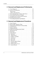
2-4 Selecting from the Advanced Menu 2-5 Selecting from the Tools Menu 2-5 2.2 Troubleshooting Flowcharts 2-6 3 Illustrated Parts Catalog 3.1 Serial Number Location 3-1 3.2 Notebook Major Components 3-2 3.3 Mass Storage Devices 3-12 3.4 Miscellaneous 3-14 Maintenance and Service Guide iii - Compaq 2200 | Service Guide - Page 4
Sequence Chart 5-2 5.3 Preparing the Notebook for Disassembly 5-4 5.4 Notebook Feet 5-9 5.5 Memory Module 5-10 5.6 Mini PCI Communications Board 5-12 5.7 Keyboard Cover 5-14 5.8 Keyboard 5-16 5.9 Switch Board 5-19 5.10 Speakers 5-21 5.11 Optical Drive 5-22 5.12 Display Assembly 5-23 - Compaq 2200 | Service Guide - Page 5
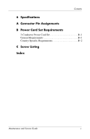
Contents 6 Specifications A Connector Pin Assignments B Power Cord Set Requirements 3-Conductor Power Cord Set B-1 General Requirements B-1 Country-Specific Requirements B-2 C Screw Listing Index Maintenance and Service Guide v - Compaq 2200 | Service Guide - Page 6
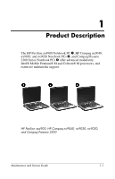
nx9020 Notebook PCs 2, and Compaq Presario 2200 Series Notebook PCs 3 offer advanced modularity, Intel® Mobile Pentium® M and Celeron® M processors, and extensive multimedia support. HP Pavilion ze4900, HP Compaq nx9040, nx9030, nx9020, and Compaq Presario 2200 Maintenance and Service Guide 1-1 - Compaq 2200 | Service Guide - Page 7
on the bottom of HP Compaq nx9000 Notebook PCs. Hnx9040 1 Key 1 2 3 4 5 6 Table 1-1 Model Naming Conventions Key U P735 X5 60 Y Cc 51 P a 2 3 4 5 6 7 8 9 10 Description Options Brand/series designator H = HP Compaq nx9040, x9030, or nx9020 Graphics memory U = UMA Processor brand and - Compaq 2200 | Service Guide - Page 8
communication/ wireless FE NIC (Intel) device g = 802.11g (includes 802.11b and g) N = none 8 RAM 51 = 512 MB 25 = 256 MB 9 Operating system H = Microsoft® Windows® XP Home P = Microsoft Windows XP Pro 10 Warranty a = 1 year on parts and labor Maintenance and Service Guide 1-3 - Compaq 2200 | Service Guide - Page 9
Pacific PK344PA UUF Thailand PK350PA AKL Hnx9040 U P725 X4 40 W Cc 25 P a Taiwan PK349PA AB0 All HP Compaq nx9000 models feature: ■ TouchPad pointing device ■ 6-cell lithium ion (Li-Ion) battery pack Hnx9040 U P725 X4 40 W CN 25 H a People's Republic of China PK165PA AB2 Hnx9040 U P725 X4 - Compaq 2200 | Service Guide - Page 10
Product Description Table 1-2 HP Compaq nx9040, nx9030, and nx9020 (Continued) Hnx9040 U P725 X4 40 D CN Cc 25 P a Taiwan PK348PA AB0 Taiwan PK347PA AB0 All HP Compaq nx9000 models feature: ■ TouchPad pointing device ■ 6-cell lithium ion (Li-Ion) battery pack Hnx9040 U P715 X4 40 D CN 25 H a - Compaq 2200 | Service Guide - Page 11
Product Description Table 1-2 HP Compaq nx9040, nx9030, and nx9020 (Continued) Hnx9040 U P715 X4 30 C Cc C320 X4 30 W CN 25 H a Japan PK157PA ABJ All HP Compaq nx9000 models feature: ■ TouchPad pointing device ■ 6-cell lithium ion (Li-Ion) battery pack Hnx9040 U C320 X4 30 W CN 25 P a Asia - Compaq 2200 | Service Guide - Page 12
Product Description Table 1-2 HP Compaq nx9040, nx9030, and nx9020 (Continued) Hnx9030 U P735 X5 40 Y Cc 51 P a France Iceland Sweden/Finland PG575ET ABF PG575ET U P715 X5 40 W Cc 51 P a French Canada PG523UA ABC United States PG523UA ABA and PH855AA ABA Maintenance and Service Guide 1-7 - Compaq 2200 | Service Guide - Page 13
Product Description Table 1-2 HP Compaq nx9040, nx9030, and nx9020 (Continued) All HP Compaq nx9000 models feature: ■ TouchPad pointing device ■ 6-cell lithium ion (Li-Ion) battery pack Hnx9030 U P715 X5 40 W U C320 X4 30 D Cc 25 P a United States PH854AA ABA 1-8 Maintenance and Service Guide - Compaq 2200 | Service Guide - Page 14
Product Description Table 1-2 HP Compaq nx9040, nx9030, and nx9020 (Continued) All HP Compaq nx9000 models feature: ■ TouchPad pointing device ■ 6-cell lithium ion (Li-Ion) battery pack Hnx9020 U C320 X5 30 W ACB PG567ET ACB PG567EA ACQ PG567EA AKR PG567ET AK8 Maintenance and Service Guide 1-9 - Compaq 2200 | Service Guide - Page 15
model ■ Diskette drive (HP Compaq nx9040 notebook model only) ■ 256-MB DDR synchronous DRAM (SDRAM) at 333 MHz, expandable to 2.0 GB or 1.0 GB, varying by notebook model ■ Microsoft® Windows® XP Home Edition or Windows XP Professional, varying by notebook model 1-10 Maintenance and Service Guide - Compaq 2200 | Service Guide - Page 16
Full-size Windows keyboard with embedded notebook models except HP Compaq nx9040) ■ External 65-watt AC adapter with 3-wire power cord ■ 6-cell or 8-cell Li-Ion battery pack ■ Altec Lansing stereo speakers with volume up and down buttons (HP Pavilion ze4900 models only) Maintenance and Service Guide - Compaq 2200 | Service Guide - Page 17
■ Support for the following optical drives: ❏ 24X Max DVD+RW/R and CD-RW Combo Drive (HP Compaq nx9040 and nx9030 select models only) ❏ 8X Max DVD-ROM Drive ❏ 24X Max CD-ROM Drive (HP Compaq nx9040, nx9030, and nx9020 select models only) ❏ 24X Max DVD/CD-RW Combo Drive ■ Connectors: ❏ External - Compaq 2200 | Service Guide - Page 18
the bottom of the notebook. Resetting the Notebook ✎ To boot from a CD, insert a bootable CD (such as a Recovery disc) into the optical drive, and then restart. Press esc when the HP logo appears, and then select the optical drive as the temporary boot device. Maintenance and Service Guide 1-13 - Compaq 2200 | Service Guide - Page 19
Description 1.4 Power Management The notebook comes with power management features that extend battery operating time and conserve power. The notebook supports the following power management features ■ Advanced Configuration and Power Management (ACPM) compliance 1-14 Maintenance and Service Guide - Compaq 2200 | Service Guide - Page 20
Product Description 1.5 External Components The external components on the front and right side of the HP Pavilion ze4900 notebook are shown below and described in Table 1-3. Front and Right-Side Components - HP Pavilion ze4900 Maintenance and Service Guide 1-15 - Compaq 2200 | Service Guide - Page 21
or blinking: The internal hard drive Electronics) drive light or an optical drive is being accessed. Hard drive bay Holds the internal hard drive. Power/standby light ■ On: Notebook is turned on. ■ Blinking: Notebook is in standby. ■ Off: Notebook is off. 1-16 Maintenance and Service Guide - Compaq 2200 | Service Guide - Page 22
external components on the front and right side of the HP Compaq nx9040, nx9030, nx9020, and Compaq Presario 2200 notebooks are shown below and described in Table 1-4. Front and Right-Side Components - HP Compaq nx9040, nx9030, nx9020, and Compaq Presario 2200 Maintenance and Service Guide 1-17 - Compaq 2200 | Service Guide - Page 23
the antennae free from obstructions. Optical drive Supports an optical disc. Battery bay Holds a battery pack. Wireless button light On: An integrated wireless device is hardware enabled. Wireless button Infrared port (select HP Compaq nx9040 notebooks only) Enables/disables an internal - Compaq 2200 | Service Guide - Page 24
the rear and left side of the HP Pavilion ze4900, HP Compaq nx9030, nx9020, and Compaq Presario 2200 notebooks are shown below and described in Table 1-5. Rear and Left-Side Components - HP Pavilion ze4900, HP Compaq nx9030, nx9020, and Compaq Presario 2200 Table 1-5 Rear and Left-Side Components - Compaq 2200 | Service Guide - Page 25
Product Description Table 1-5 Rear and Left-Side Components HP Pavilion ze4900, HP Compaq nx9030, nx9020, and Compaq Presario 2200 (Continued) Item 5 6 7 8 9 10 11 12 13 14 15 16 Component External monitor port Exhaust vents (2) Security cable slot RJ-11 (modem) jack PC Card slot(s) (1 - Compaq 2200 | Service Guide - Page 26
HP Compaq nx9040 notebook are shown below and described in Table 1-6. Rear and Left-Side Components - HP Compaq nx9040 Item 1 2 3 4 5 6 Table 1-6 Rear and Left-Side Components HP Compaq nx9040 Component Power connector USB connectors as keyboard or mouse. Maintenance and Service Guide 1-21 - Compaq 2200 | Service Guide - Page 27
15 16 17 18 19 Table 1-6 Rear and Left-Side Components HP Compaq nx9040 (Continued) Component External monitor port Exhaust vents (2) Security system volume. Decreases system volume. Mutes or restores volume. On: Volume is muted. Supports a 3.5-inch diskette. 1-22 Maintenance and Service Guide - Compaq 2200 | Service Guide - Page 28
Product Description The notebook keyboard components on the HP Pavilion ze4900 notebook are shown below and described in Table 1-7. Keyboard Components - HP Pavilion ze4900 Maintenance and Service Guide 1-23 - Compaq 2200 | Service Guide - Page 29
Product Description Item 1 2 3 4 5 6 7 8 Table 1-7 Keyboard Components HP Pavilion ze4900 Component Function num lock key Enables numeric lock, turns on the embedded numeric keypad, and turns on the num lock light. Keypad keys (15) In Windows, can be used like the keys on an external - Compaq 2200 | Service Guide - Page 30
Product Description The notebook keyboard components on the HP Compaq nx9040, nx9030, nx9020, and Compaq Presario 2200 notebooks are shown below and described in Table 1-8. Keyboard Components - HP Compaq nx9040, nx9030, nx9020, and Compaq Presario 2200 Maintenance and Service Guide 1-25 - Compaq 2200 | Service Guide - Page 31
Description Item 1 2 3 4 5 6 7 8 Table 1-8 Keyboard Components HP Compaq nx9040, nx9030, nx9020, and Compaq Presario 2200 Component Function num lock key Enables numeric lock, turns on the embedded numeric keypad, and turns on the num lock light. Keypad keys (15) In Windows, can be used - Compaq 2200 | Service Guide - Page 32
Product Description The notebook top components on the HP Pavilion ze4900 notebook are shown below and described in Table 1-9. Top Components - HP Pavilion ze4900 Maintenance and Service Guide 1-27 - Compaq 2200 | Service Guide - Page 33
on the notebook. ■ On, briefly press to initiate Hibernation. ■ In Standby, briefly press to resume from Standby. ■ In Hibernation, briefly press to restore from Hibernation. Speakers (2) Produces stereo sound. Caps lock light On: TouchPad is enabled. 1-28 Maintenance and Service Guide - Compaq 2200 | Service Guide - Page 34
Product Description The notebook top components on the HP Compaq nx9040, nx9030, nx9020, and Compaq Presario 2200 notebooks are shown below and described in Table 1-10. Top Components - HP Compaq nx9040, nx9030, nx9020, and Compaq Presario 2200 Maintenance and Service Guide 1-29 - Compaq 2200 | Service Guide - Page 35
HP Compaq nx9040, nx9030, nx9020, and Compaq Presario 2200 Component Function Power button When the notebook is ■ Off, press to turn on the notebook. ■ On, briefly press to initiate Hibernation. ■ In Standby, briefly press to resume from Standby. ■ In Hibernation, briefly press to restore - Compaq 2200 | Service Guide - Page 36
Product Description The external components on the bottom of all notebook models are shown below and described in Table 1-11. Bottom Components Maintenance and Service Guide 1-31 - Compaq 2200 | Service Guide - Page 37
remove the device to restore notebook functionality. Then contact Customer Care. Contains 2 memory slots that support replaceable memory modules. The number of preinstalled memory modules varies by notebook model. Holds the internal hard drive. Holds a battery pack. Releases a battery pack from the - Compaq 2200 | Service Guide - Page 38
disassembly steps. The system board provides the following device connections: ■ Memory module ■ Mini PCI communications devices ■ Hard drive ■ Display ■ Keyboard and TouchPad ■ Audio ■ Intel Pentium M and Celeron M processors ■ Fan ■ PC Card Ä CAUTION: To properly ventilate the notebook, allow at - Compaq 2200 | Service Guide - Page 39
trained by HP should repair this equipment. All troubleshooting and repair system information and customization utility that can be used even when your operating system is not working or will not load. This utility includes settings that are not available in Windows. Maintenance and Service Guide - Compaq 2200 | Service Guide - Page 40
Troubleshooting Using Computer Setup Information and settings in Computer Setup are accessed from the Main, Security, Advanced, or Tools menus: 1. Turn on or restart the notebook or Tools menu. 3. To close Computer Setup and restart the notebook: ❏ Select Exit > Exit Saving Changes, and then press - Compaq 2200 | Service Guide - Page 41
Menu Troubleshooting Select System Information Table 2-1 Main Menu To Do This ■ Change the system time and system date. ■ View identification information about the notebook. ■ View specification information about the processor, memory and cache size, and system ROM. Maintenance and Service Guide - Compaq 2200 | Service Guide - Page 42
) the notebook. Password Options (Password options can be selected only when a power-on password has been drive startup* ■ CD-ROM or diskette startup ✎ Settings for a DVD-ROM can be entered in the CD-ROM field. *Not applicable to SuperDisk LS-120 drives. 2-4 Maintenance and Service Guide - Compaq 2200 | Service Guide - Page 43
abilities. Displays the amount of video memory available on the notebook. Selecting from the Tools Menu Select Hard Drive Self Test Table 2-4 Tools Menu To Do This Run a quick comprehensive self test on hard drives in the system that support the test features. Maintenance and Service Guide 2-5 - Compaq 2200 | Service Guide - Page 44
Drive" "Flowchart 2.13-No OS Loading, CD-ROM or DVD-ROM Drive" "Flowchart 2.14-No Audio" "Flowchart 2.15-Nonfunctioning Device" "Flowchart 2.16-Nonfunctioning Keyboard" "Flowchart 2.17-Nonfunctioning Pointing Device" "Flowchart 2.18-No Network/Modem Connection" 2-6 Maintenance and Service Guide - Compaq 2200 | Service Guide - Page 45
? (no boot) Y N Is the OS loading? Y N Is there sound? Y Check LED board, speaker connections. Y Go to "Flowchart 2.6-No Video, Part 1." Go to Y "Flowchart 2.8-No Operating System (OS) Loading." Y Go to "Flowchart 2.14-No Audio." N All drives working? N Keyboard/ pointing device working - Compaq 2200 | Service Guide - Page 46
Troubleshooting Flowchart 2.2-No Power, Part 1 No power (power light is off). N Power up on battery power? Y N Power up on AC power? Y Done Reset battery pack. N Power up on battery the notebook can be reset using either the lid switch or the main power switch. 2-8 Maintenance and Service Guide - Compaq 2200 | Service Guide - Page 47
in battery socket and clean if necessary. Y Power on? N Done Check battery by recharging it, moving it to another notebook, or replacing it. N Power on? Y Replace power supply (if applicable). N Done Power on? Y Go to "Flowchart 2.4-No Power, Part 3." Done Maintenance and Service Guide - Compaq 2200 | Service Guide - Page 48
Troubleshooting Flowchart 2.4-No Power, Part 3 Continued from "Flowchart 2.3-No Power, Part 2." Plug directly into AC outlet. Y Power LED on? N Reseat AC adapter in notebook and at power source. Y Done Power on? N N Power outlet active? Y Replace power cord. Y Power on? N Done Try different - Compaq 2200 | Service Guide - Page 49
Replace the following items (if applicable). Check notebook operation after each replacement: 1. Internal DC-DC converter* 2. Internal AC adapter 3. Processor board* 4. System board* *NOTE: Replace these items as a set to prevent shorting out among components. Maintenance and Service Guide 2-11 - Compaq 2200 | Service Guide - Page 50
Troubleshooting Flowchart 2.6-No Video, Part 1 notebook and notebook display (if applicable) 2. Inverter board (if applicable) 3. Display 4. System board N Video OK? Y Try another display. N Internal and external video OK? Y Replace system board. Done Done 2-12 Maintenance and Service Guide - Compaq 2200 | Service Guide - Page 51
Troubleshooting Flowchart 2.7-No Video, Part 2 Continued from "Flowchart 2.6-No Video, Part 1." Adjust display ? N Try another external monitor. Done Y Internal and external video OK? N Adjust external monitor display. Replace system board. Done Done Maintenance and Service Guide 2-13 - Compaq 2200 | Service Guide - Page 52
Troubleshooting Flowchart 2.8-No Operating System (OS) Loading No OS loading.* Reseat power cord at power outlet. No OS loading from hard drive, go to "Flowchart 2.9-No OS Loading, Hard Drive, Part 1." No OS loading from diskette drive, go to "Flowchart 2.12-No OS Loading, Diskette Drive." No OS - Compaq 2200 | Service Guide - Page 53
Troubleshooting Flowchart 2.9-No OS Loading, Hard Drive, Part 1 OS not loading from hard drive. Y Nonsystem disk message? N Reseat external hard drive. Y OS loading? N N Boot from CD? Y Check the Setup utility for correct booting order. N Boot from hard drive? Y Done Go to "Flowchart 2.10-No OS - Compaq 2200 | Service Guide - Page 54
then format hard drive to bootable C:\ prompt. Hard drive formatted? Y Format hard drive and bring to a bootable Y C:\ prompt. Notebook booted? N Go to "Flowchart 2.11-No OS Loading, Hard Drive, Part 3." Load OS using System Restore CD (if applicable). 2-16 Maintenance and Service Guide - Compaq 2200 | Service Guide - Page 55
Troubleshooting Flowchart 2.11-No OS Loading, Hard Drive, Part 3 Continued from "Flowchart 2.10-No OS Loading, Hard Drive, Part 2." N System files on hard drive? Y Install OS and reboot. Y Virus on hard drive? N Run SCANDISK and check for bad sectors. N Can bad sectors be fixed? Y Clean virus. - Compaq 2200 | Service Guide - Page 56
disk error? N Y Reset the notebook. Refer to Section 1.3, "Resetting the N Notebook," for instructions. OS loading? 1. Replace diskette drive. 2. Replace system board. Done Change boot priority using the Setup utility. Go to "Flowchart 2.15-Nonfunctioning Device." 2-18 Maintenance and Service - Compaq 2200 | Service Guide - Page 57
Troubleshooting Flowchart 2.13-No OS Loading, CD-ROM or DVD-ROM Drive No OS loading from CD-ROM or DVD-ROM Drive. N Disc in drive? Y Y N Bootable disc in drive? Install bootable disc and reboot notebook. Install bootable disc. Try another bootable disc. Y Boots from CD or DVD? N Done - Compaq 2200 | Service Guide - Page 58
and set configuration in OS. Connect to external speaker. N Audio? Y Replace audio Y board and speaker connections Audio? in notebook (if applicable). N Done 1. Replace internal speakers. 2. Replace audio board (if applicable). 3. Replace system board. 2-20 Maintenance and Service Guide - Compaq 2200 | Service Guide - Page 59
? Y Y Any physical device detected? N Replace hard drive. Replace NIC. If integrated NIC, replace system board. Fix or replace broken item. Go to "Flowchart 2.8-No Operating System (OS) Loading." N Device boots properly? Y Done Replace diskette drive. Done Maintenance and Service Guide 2-21 - Compaq 2200 | Service Guide - Page 60
operating properly. Connect notebook to good external keyboard. N External device works? Y Replace system board. Reseat internal keyboard connector (if applicable). N OK? Y Replace internal keyboard or cable. Y Done OK? N Replace system board. Done 2-22 Maintenance and Service Guide - Compaq 2200 | Service Guide - Page 61
. Connect notebook to good external pointing device. N External device works? Y Replace system board. Reseat internal pointing device connector (if applicable). N OK? Y Replace internal pointing device or cable. Y Done OK? N Replace system board. Done Maintenance and Service Guide 2-23 - Compaq 2200 | Service Guide - Page 62
all power from the notebook and open. Replace jack or have jack activated. Connect to nondigital line. Reload drivers and reconfigure. Reseat NIC/modem (if applicable). Y OK? N Replace NIC/modem (if applicable). Y OK? N Done Done Replace system board. 2-24 Maintenance and Service Guide - Compaq 2200 | Service Guide - Page 63
breakdown and a reference for spare part numbers and option part numbers. 3.1 Serial Number Location When ordering parts or requesting information, provide the notebook serial number and model number located on the bottom of the notebook. Serial Number Location Maintenance and Service Guide 3-1 - Compaq 2200 | Service Guide - Page 64
Illustrated Parts Catalog 3.2 Notebook Major Components Notebook Major Components 3-2 Maintenance and Service Guide - Compaq 2200 | Service Guide - Page 65
Keyboard covers (includes speaker grilles and switch board) for use on HP Pavilion ze4900 notebook models for use on HP Compaq nx9040, nx9030, and nx9020 notebook models for use on Compaq Presario 2200 notebook models 371802-001 371804-001 371803-001 Switch board Maintenance and Service Guide - Compaq 2200 | Service Guide - Page 66
Illustrated Parts Catalog Notebook Major Components 3-4 Maintenance and Service Guide - Compaq 2200 | Service Guide - Page 67
HP Compaq nx9040 notebook models for use in HP Compaq nx9030 and nx9020 notebook models for use in Compaq Presario 2200 notebook models 371799-001 373291-001 371801-001 371800-001 4b Speakers 5 Heat sink 371796-001 Thermal Pad Kit (not illustrated) 371809-001 Maintenance and Service Guide - Compaq 2200 | Service Guide - Page 68
Illustrated Parts Catalog Notebook Major Components 3-6 Maintenance and Service Guide - Compaq 2200 | Service Guide - Page 69
digital connectors for use on HP Compaq nx9040 notebook models 371793-001 371794-001 371795-001 Hard drive guide (not illustrated) 371798-001 8a Diskette drive (for use on HP Compaq nx9040 notebook models only) 8b Diskette drive cover 371779-001 371805-001 Maintenance and Service Guide - Compaq 2200 | Service Guide - Page 70
Illustrated Parts Catalog Notebook Major Components 3-8 Maintenance and Service Guide - Compaq 2200 | Service Guide - Page 71
for use on notebook models without infrared transceiver 373017-001 373016-001 11 Optical drives 4X Max DVD+R/RW 2X Max DVD+R/RW 24X Max DVD/CD-RW Combo Drive 8X Max DVD-ROM Drive 24X Max CD-ROM Drive 371784-001 371783-001 371782-001 371781-001 371780-001 Maintenance and Service Guide 3-9 - Compaq 2200 | Service Guide - Page 72
Illustrated Parts Catalog Notebook Major Components 3-10 Maintenance and Service Guide - Compaq 2200 | Service Guide - Page 73
-001 373027-001 14 Memory modules 512-MB DDR 256-MB DDR 128-MB DDR 371775-001 371774-001 371773-001 15a Memory module compartment cover and 15b Mini PCI compartment cover 371806-001 16 Battery packs 8-cell Li-Ion 6-cell Li-Ion 371786-001 371785-001 Maintenance and Service Guide 3-11 - Compaq 2200 | Service Guide - Page 74
Illustrated Parts Catalog 3.3 Mass Storage Devices Mass Storage Devices 3-12 Maintenance and Service Guide - Compaq 2200 | Service Guide - Page 75
hard drive bezel) 60-GB 40-GB 30-GB Optical drives 4X Max DVD+R/RW 2X Max DVD+R/RW 24X Max DVD/CD-RW Combo Drive 8X Max DVD-ROM Drive 24X Max CD-ROM Drive Spare Part Number 371779-001 371778-001 371777-001 371776-001 371784-001 371783-001 371782-001 371781-001 371780-001 Maintenance and Service - Compaq 2200 | Service Guide - Page 76
Spare Part Number Logo Kit 371812-001 65-watt AC adapter 371790-001 Power cords Australia Brazil Denmark Europe Israel Italy screws; refer to Appendix C, "Screw Listing," for more information on screw specifications and usage). 373294-001 ■ PM2.0×9.0 screw ■ PM2.0×8.0 screw ■ PM2.0×6.0 - Compaq 2200 | Service Guide - Page 77
tools to complete the removal and replacement procedures: ■ Magnetic screwdriver ■ Phillips P0 screwdriver ■ 5.0-mm socket for system board screwlocks ■ Flat-bladed screwdriver ■ Tool kit-includes connector removal tool, loopback plugs, and case utility tool Maintenance and Service Guide 4-1 - Compaq 2200 | Service Guide - Page 78
. Apply pressure only at the points designated in the maintenance instructions. Cables and Connectors Ä CAUTION: When servicing the notebook, ensure that cables are placed in their proper locations during flex cables with extreme care; these cables tear easily. 4-2 Maintenance and Service Guide - Compaq 2200 | Service Guide - Page 79
: ■ Before removing or inserting a hard drive, shut down the notebook. If you are unsure whether the notebook is off or in Hibernation, turn the notebook on, and then shut it down through the operating system. ■ Before removing a diskette drive or optical drive, ensure that a diskette or disc - Compaq 2200 | Service Guide - Page 80
ground and that proper materials are selected to avoid static charging. When grounding is not possible, use an ionizer to dissipate electric charges. 4-4 Maintenance and Service Guide - Compaq 2200 | Service Guide - Page 81
. ■ When seated, wear a wrist strap connected to a grounded system. Wrist straps are flexible straps with a minimum of one megohm ± snugly against the skin at all times. On grounded mats with banana-plug connectors, use alligator clips to connect a wrist strap. ■ When standing, use Service Guide 4-5 - Compaq 2200 | Service Guide - Page 82
of one megohm resistance ■ Static-dissipative tables or floor mats with hard ties to the ground ■ Field service kits ■ Static awareness labels ■ Material-handling packages ■ Nonconductive plastic the electrostatic voltage levels generated by different activities. 4-6 Maintenance and Service Guide - Compaq 2200 | Service Guide - Page 83
4-2 Static-Shielding Materials Material Antistatic plastic Carbon-loaded plastic Metallized laminate Use Bags Floor mats Floor mats Voltage Protection Level 1,500 V 7,500 V 5,000 V Maintenance and Service Guide 4-7 - Compaq 2200 | Service Guide - Page 84
," for detailed information on screw sizes, locations, and usage. 5.1 Serial Number Report the notebook serial number to HP when requesting information or ordering spare parts. The serial number is located on the bottom of the notebook. Serial Number Location Maintenance and Service Guide 5-1 - Compaq 2200 | Service Guide - Page 85
notebook for disassembly Battery pack Hard drive 0 2 to remove hard drive 2 to remove hard drive bezel Notebook feet 0 Memory module 2 loosened Mini PCI communications board 2 loosened Keyboard cover 2 Keyboard 4 Switch board 2 on all notebook models except HP Pavilion ze4900 1 on HP - Compaq 2200 | Service Guide - Page 86
) Section 5.15 5.16 5.17 5.18 5.19 Description Processor Wireless button board Diskette drive Diskette drive cover System board # of Screws Removed 0 2 2 2 8 screws 2 screwlocks on all notebook models except HP Compaq nx9040 6 screwlocks on HP Compaq nx9040 Maintenance and Service Guide 5-3 - Compaq 2200 | Service Guide - Page 87
, turn the computer on and then shut it down through the operating system. 2. Disconnect all external devices connected to the notebook. 3. Disconnect the power cord. Spare Part Number Information Battery packs 8-cell Li-Ion 6-cell Li-Ion 371786-001 371785-001 5-4 Maintenance and Service Guide - Compaq 2200 | Service Guide - Page 88
and hold the battery release latch 1 toward the back of the notebook. c. Use the notch in the battery bezel to slide the battery pack to the left 2. d. Remove the battery pack. Removing the Battery Pack Reverse the above procedure to install the battery pack. Maintenance and Service Guide 5-5 - Compaq 2200 | Service Guide - Page 89
be used to replace the hard drive rubber screw covers. b. Remove the 2 PM2.0×6.0 screws 2 that secure the hard drive to the notebook. c. Use the notch in the hard drive bezel to slide the hard drive forward 3. d. Remove the hard drive. Removing the Hard Drive 5-6 Maintenance and Service Guide - Compaq 2200 | Service Guide - Page 90
Removal and Replacement Procedures e. Remove the 2 PM1.5×5.0 shoulder screws 1 that secure the hard drive bezel to the hard drive. f. Remove the hard drive bezel 2. Removing the Hard Drive Bezel Maintenance and Service Guide 5-7 - Compaq 2200 | Service Guide - Page 91
g. Remove the 4 PM2.5×4.0 screws 1 that secure the hard drive frame to the hard drive. h. Remove the hard drive frame 2. i. Remove the hard drive connector 3. Disassembling the hard drive Reverse the above procedure to reassemble and install the hard drive. 5-8 Maintenance and Service Guide - Compaq 2200 | Service Guide - Page 92
and Replacement Procedures 5.4 Notebook Feet The notebook feet are adhesive-backed rubber pads. Spare part number 371808-001 should be used to replace the notebook feet. The feet attach to the base enclosure as illustrated below. Replacing the Notebook Feet Maintenance and Service Guide 5-9 - Compaq 2200 | Service Guide - Page 93
the back edge of the memory module compartment cover and swing it forward 2. 4. Remove the memory module compartment cover. ✎ Spare part number 371806-001 should be used to replace the memory module compartment cover. Removing the Memory Module Compartment Cover 5-10 Maintenance and Service Guide - Compaq 2200 | Service Guide - Page 94
secure the memory module to the memory module socket. (The module rises up). 6. Remove the memory module by pulling it away from the memory module socket at a 45-degree angle 2. Removing a Memory Module Reverse the above procedure to install a memory module. Maintenance and Service Guide 5-11 - Compaq 2200 | Service Guide - Page 95
001 373026-001 373027-001 1. Prepare the notebook for disassembly (Section 5.3). 2. Loosen the 2 PM2.0×4.0 screws 1 that secure the Mini PCI compartment cover to the notebook. 3. Lift the front edge of the Removing the Mini PCI Communications Compartment Cover 5-12 Maintenance and Service Guide - Compaq 2200 | Service Guide - Page 96
away from the socket at a 45-degree angle 3. Removing a Mini PCI Communications Board Reverse the above procedure to install a Mini PCI communications board. Maintenance and Service Guide 5-13 - Compaq 2200 | Service Guide - Page 97
Spare Part Number Information For use on HP Pavilion ze4900 notebook models For use on HP Compaq nx9040, nx9030, and nx9020 notebook models For use on Compaq Presario 2200 notebook models 371802-001 371804-001 371803-001 1. Prepare the notebook for disassembly (Section 5.3). 2. Position the - Compaq 2200 | Service Guide - Page 98
cover from the notebook. 9. Press and hold the home key 4 and use a flat tool to separate the cover from the notebook. 10. Lift the cover up to remove it from the notebook 5. Removing the Keyboard Cover Reverse the above procedure to install an keyboard cover. Maintenance and Service Guide 5-15 - Compaq 2200 | Service Guide - Page 99
Removal and Replacement Procedures 5.8 Keyboard Spare Part Number Information Belgium Brazil Czech Republic Denmark 371787-281 371787-141 371787-031 371787-001 1. Prepare the notebook for disassembly (Section 5.3). 2. Remove the keyboard cover (Section 5.7). 5-16 Maintenance and Service Guide - Compaq 2200 | Service Guide - Page 100
Removal and Replacement Procedures 3. Remove the 3 PM2.0×4.0 screws 1 and 1 PM2.0×3.0 screw 2 that secure the keyboard to the notebook. 4. Lift the back edge of the keyboard and swing it forward until it rests on the palm rest 3. Releasing the Keyboard Maintenance and Service Guide 5-17 - Compaq 2200 | Service Guide - Page 101
Removal and Replacement Procedures 5. Release the zero insertion force (ZIF) connector 1 to which the keyboard cable is attached and disconnect the cable 2. 6. Remove the keyboard. Removing the Keyboard Reverse the above procedure to install the keyboard. 5-18 Maintenance and Service Guide - Compaq 2200 | Service Guide - Page 102
information. 1. Prepare the notebook for disassembly (Section 5.3). 2. Remove the keyboard cover (Section 5.7). 3. Remove the keyboard (Section 5.8). 4. Disconnect the display lid switch 1 and speaker cables 2 from the switch board. Removing the Switch Board Maintenance and Service Guide 5-19 - Compaq 2200 | Service Guide - Page 103
screws 3 that secure the switch board to the notebook. 6. Lift the right side of the switch board 4 to disconnect the board from the system board. 7. Remove the switch board. Removing the Switch Board Reverse the above procedure to install the switch board. 5-20 Maintenance and Service Guide - Compaq 2200 | Service Guide - Page 104
. 1. Prepare the notebook for disassembly (Section 5.3). 2. Remove the keyboard cover (Section 5.7). 3. Remove the keyboard (Section 5.8). 4. notebook. 6. Remove the left and right speakers 3. Removing the Speakers Reverse the above procedure to install the speakers. Maintenance and Service Guide - Compaq 2200 | Service Guide - Page 105
PM2.0×4.0 screw 2 that secure the optical drive to the notebook. 5. Push on the back of the optical drive to disconnect it from the system board. 6. Remove the optical drive 3. Removing the Optical Drive Reverse the above procedure to install the optical drive. 5-22 Maintenance and Service Guide - Compaq 2200 | Service Guide - Page 106
Compaq Presario 2200 notebook models 15.0-inch, XGA 14.1-inch, XGA 371770-001 371769-001 Display screw covers 371813-001 1. Prepare the notebook for disassembly (Section 5.3). 2. Remove the keyboard cover (Section 5.7). 3. Remove the keyboard (Section 5.8). Maintenance and Service Guide 5-23 - Compaq 2200 | Service Guide - Page 107
Removal and Replacement Procedures 4. Remove the 2 PM2.0×5.0 screws that secure the wireless antenna boards to the notebook. Removing the Wireless Antenna Boards 5-24 Maintenance and Service Guide - Compaq 2200 | Service Guide - Page 108
Removal and Replacement Procedures 5. Disconnect the display cable 1 from the system board. 6. Remove the 6 PM2.0×6.0 screws 2 that secure the display to the notebook. Removing the Display Assembly Screws Maintenance and Service Guide 5-25 - Compaq 2200 | Service Guide - Page 109
the display perpendicular to the notebook. 9. Remove the 2 PM2.0×6.0 screws 1 that secure the display to the notebook. 10. Lift the display straight up and remove it 2. Removing the Display Assembly Reverse the above procedure to install the display assembly. 5-26 Maintenance and Service Guide - Compaq 2200 | Service Guide - Page 110
Compaq Presario 2200 notebook models 371799-001 373291-001 371801-001 371800-001 1. Prepare the notebook for disassembly (Section 5.3) and remove the following components: ❏ Keyboard cover (Section 5.7) ❏ Keyboard (Section 5.8) ❏ Switch board (Section 5.9) ❏ Speakers (Section 5.10) ❏ Optical drive - Compaq 2200 | Service Guide - Page 111
be used to replace the top cover rubber screw covers. 4. Remove the 15 PM2.0×6.0 screws 2 that secure the top cover to the notebook. 5. Remove the PM2.0×4.0 screw 3 in the hard drive bay that secures the top cover to the notebook. Removing the Top Cover Screws 5-28 Maintenance and Service Guide - Compaq 2200 | Service Guide - Page 112
-side up with the rear panel toward you. 7. Remove the PM2.0×8.0 screw 1 and the PM2.0×9.0 screw 2 that secure the top cover to the notebook. 8. Remove the 2 PM2.0×4.0 screws 3 that secure the top cover to the notebook. Removing the Top Cover Screws (continued) Maintenance and Service Guide 5-29 - Compaq 2200 | Service Guide - Page 113
Procedures 9. Release the ZIF connector 1 to which the TouchPad cable is attached and disconnect the cable 2 from the system board. 10. Lift the top cover straight up and remove it 3. Removing the Top Cover Reverse the above procedure to install the top cover. 5-30 Maintenance and Service Guide - Compaq 2200 | Service Guide - Page 114
(Section 5.3) and remove the following components: ❏ Keyboard cover (Section 5.7) ❏ Keyboard (Section 5.8) ❏ Switch board (Section 5.9) ❏ Speakers (Section 5.10) ❏ Optical drive (Section 5.11) ❏ Display assembly (Section 5.12) ❏ Top cover (Section 5.13) Maintenance and Service Guide 5-31 - Compaq 2200 | Service Guide - Page 115
and Replacement Procedures 2. Disconnect the fan cable 1 from the system board. 3. Remove the 3 PM1.5×5.0 screws 2 that secure the heat sink to the notebook. 4. Remove the heat sink 3. Removing the Heat Sink Reverse the above procedure to install the heat sink. 5-32 Maintenance and Service Guide - Compaq 2200 | Service Guide - Page 116
remove the following components: ❏ Keyboard cover (Section 5.7) ❏ Keyboard (Section 5.8) ❏ Switch board (Section 5.9) ❏ Speakers (Section 5.10) ❏ Optical drive (Section 5.11) ❏ Display assembly (Section 5.12) ❏ Top cover (Section 5.13) ❏ Heat sink (Section 5.14) Maintenance and Service Guide 5-33 - Compaq 2200 | Service Guide - Page 117
aligned in the rear left corner when you install the processor. Removing the Processor Reverse the above procedure to install the processor. 5-34 Maintenance and Service Guide - Compaq 2200 | Service Guide - Page 118
remove the following components: ❏ Keyboard cover (Section 5.7) ❏ Keyboard (Section 5.8) ❏ Switch board (Section 5.9) ❏ Speakers (Section 5.10) ❏ Optical drive (Section 5.11) ❏ Display assembly (Section 5.12) ❏ Top cover (Section 5.13) ❏ Heat sink (Section 5.14) Maintenance and Service Guide 5-35 - Compaq 2200 | Service Guide - Page 119
cable 1 from the system board. 3. Remove the 2 PM2.0×4.0 screws 2 that secure the wireless button board to the notebook. 4. Remove the wireless button board 3. Removing the Wireless Button Board Reverse the above procedure to install the wireless button board. 5-36 Maintenance and Service Guide - Compaq 2200 | Service Guide - Page 120
✎ This section applies only to HP Compaq nx9040 notebook models. Diskette drive Spare Part Number Information 371779-001 1. Prepare the notebook for disassembly (Section 5.3) and remove the following components: ❏ Keyboard cover (Section 5.7) ❏ Keyboard (Section 5.8) ❏ Switch board (Section - Compaq 2200 | Service Guide - Page 121
the low insertion force (LIF) connector on the system board. 3. Remove the 2 PM2.0×4.0 screws 2 that secure the diskette drive to the notebook. 4. Remove the diskette drive 3. Removing the Diskette Drive Reverse the above procedure to install the diskette drive. 5-38 Maintenance and Service Guide - Compaq 2200 | Service Guide - Page 122
and Replacement Procedures 5.18 Diskette Drive Cover ✎ This section applies to HP Pavilion ze4900, HP Compaq nx9030 and nx9020, and Compaq Presario 2200 notebook models. Spare Part Number Information Diskette drive cover 371805-001 1. Prepare the notebook for disassembly (Section 5.3) and remove - Compaq 2200 | Service Guide - Page 123
Removal and Replacement Procedures 2. Remove the 2 PM2.0×4.0 screws 1 that secure the diskette drive cover to the notebook. 3. Remove the diskette drive cover 2. Removing the Diskette Drive Cover Reverse the above procedure to install the diskette drive cover. 5-40 Maintenance and Service Guide - Compaq 2200 | Service Guide - Page 124
use on HP Compaq nx9040 notebook models Hard drive guide (not illustrated) 371793-001 371794-001 371795-001 371798-001 ✎ When replacing the system board, ensure that the following components are removed from the defective system board and installed on the replacement system board: ■ Memory modules - Compaq 2200 | Service Guide - Page 125
screws 2 that secure the system board to the base enclosure. 4. Remove the hard drive guide 3. ✎ Spare part number 371798-001 should be used to replace the hard drive guide. 5. Remove the 2 PM1.5×18.0 PC Card assembly screws 4. Removing the System Board Screws 5-42 Maintenance and Service Guide - Compaq 2200 | Service Guide - Page 126
and nx9020, and Compaq Presario 2200 notebook models. 6. Remove the 2 HM5.0×9.0 locks on each side of the external monitor port. Removing the System Board Screwlocks - HP Pavilion ze4900, HP Compaq nx9030 and nx9020, and Compaq Presario 2200 Notebook Models Only Maintenance and Service Guide 5-43 - Compaq 2200 | Service Guide - Page 127
and Replacement Procedures ✎ Step 7 applies only to HP Compaq nx9040 models. 7. Remove the 6 HM5.0×9.0 screwlocks on each side of the parallel, serial, and external monitor ports. Removing the System Board Screwlocks - HP Compaq nx9040 Notebook Models Only 5-44 Maintenance and Service Guide - Compaq 2200 | Service Guide - Page 128
. 9. Lift the rear edge of the system board and swing it up 2 until the board rests at a 45-degree angle. 10. Slide the system board away from the base enclosure at an angle 3. Removing the System Board Reverse the above procedure to install the system board. Maintenance and Service Guide 5-45 - Compaq 2200 | Service Guide - Page 129
This chapter provides physical and performance specifications. Table 6-1 Notebook Dimensions with 15.0-inch display Height Width Depth with 14.1-inch display Height Width Depth Weight (varies by configuration) with 15.0-inch display and 8-cell battery pack with 14.1-inch display and - Compaq 2200 | Service Guide - Page 130
sweep rate 1.50 g zero-to-peak, 10 to 500 Hz, 0.5 oct/min sweep rate ✎ Applicable product safety standards specify thermal limits for plastic surfaces. The notebook operates well within this range of temperatures. 6-2 Maintenance and Service Guide - Compaq 2200 | Service Guide - Page 131
Specifications Table 6-2 15.0-inch, XGA, TFT Display Dimensions Height Width Diagonal Number of colors Contrast ratio Brightness Pixel resolution 0.264 × 0.264 mm 1024 × 768 RGB vertical stripe Edge lit 80 × 25 5.5 W +/-35° horizontal, +15/-35° vertical typical Maintenance and Service Guide 6-3 - Compaq 2200 | Service Guide - Page 132
Specifications Table 6-3 14.1-inch, XGA, TFT Display Dimensions Height Width Diagonal Number of colors Contrast ratio Brightness Pixel resolution 0.279 × 0.279 mm 1024 × 768 RGB vertical stripe Edge lit 80 × 25 4 W +/-40° horizontal, +20/-40° vertical typical 6-4 Maintenance and Service Guide - Compaq 2200 | Service Guide - Page 133
(41°F to 131°F) (41°F to 131°F) ✎ Certain restrictions and exclusions apply. Consult Customer Care for details. *1 GB = 1 billion bytes when referring to hard drive storage capacity. Accessible capacity is less. †Actual drive specifications may differ slightly. Maintenance and Service Guide 6-5 - Compaq 2200 | Service Guide - Page 134
Specifications Table 6-5 Primary 6-cell, Li-Ion Battery Pack Dimensions Height Width Depth Weight Energy Voltage Amp-hour capacity Watt-hour capacity Temperature Operating Nonoperating 45°C 0°C to 60°C .79 in 3.70 in 5.28 in .75 lb 41°F to 113°F 32°F to 140°F 6-6 Maintenance and Service Guide - Compaq 2200 | Service Guide - Page 135
Battery Pack Dimensions Height Width Depth Weight Energy Voltage Amp-hour capacity Watt-hour capacity Temperature Operating Nonoperating 2.00 cm 9.40 cm 13.40 cm .34 kg 14.4 V 4.4 Ah 65 Wh 5°C to 45°C 0°C to 60°C .79 in 3.70 in 5.28 in .75 lb 41°F to 113°F 32°F to 140°F Maintenance and Service - Compaq 2200 | Service Guide - Page 136
Specifications Table 6-7 24X Max DVD+RW/R and CD-RW Drive Applicable disk Center hole diameter Disk diameter Standard disc Mini disc Disk thickness Track pitch Access time Random Full stroke Audio output level at 1X DVD rate) 16.6 MB/s < 15 seconds < 6 seconds 6-8 Maintenance and Service Guide - Compaq 2200 | Service Guide - Page 137
Specifications Table 6-8 24X Max DVD/CD-RW Combo Drive Applicable disk Center hole diameter Disk diameter Standard disc Mini disc Disk thickness Track pitch Access time Random Full stroke Audio output 0.047 in < 150 ms < 225 ms Audio-out, 0.7 Vrms 128 KB/s Maintenance and Service Guide 6-9 - Compaq 2200 | Service Guide - Page 138
Specifications Table 6-8 24X Max DVD/CD-RW Combo Drive (Continued) Data transfer rate CD-R (24X) CD-RW (10X) CD-ROM (24X) DVD (8X) Multiword DMA mode 2 Startup time Stop at 1X CD rate) 10,800 KB/s (1352 KB/s at 1X DVD rate) 16.6 MB/s < 15 seconds < 6 seconds 6-10 Maintenance and Service Guide - Compaq 2200 | Service Guide - Page 139
Specifications Table 6-9 8X MAX DVD-ROM Drive Applicable disk Center hole diameter Disk diameter Standard disc Mini disc Disk thickness Track pitch Access time Random DVD media Full stroke DVD < 150 ms < 225 ms < 110 ms < 200 ms Audio-out, 0.7 Vrms 512 KB/s Maintenance and Service Guide 6-11 - Compaq 2200 | Service Guide - Page 140
Specifications Table 6-9 8X MAX DVD-ROM Drive (Continued) Data transfer rate Max 24X CD Max 8X DVD 3600 KB/s (150 KB/s at 1X CD rate) 10,800 KB/s (1352 KB/s at 1X DVD rate) Multiword DMA mode 2 Startup time Stop time 16.6 MB/s < 10 seconds < 3 seconds Table 6-10 System DMA Hardware DMA - Compaq 2200 | Service Guide - Page 141
Standard 101-/102-Key or Microsoft Natural Keyboard Cascaded Intel 82801DB/DBM USB2 Enhanced Host Controller-24CD COM1 Conexant AC-Link Audio Intel 82801DB/DBM SMBus Controller-24C3 Soft V92 Data Fax Modem with SmartCP Diskette drive Parallel port System CMOS/real time clock Microsoft ACPI-compliant - Compaq 2200 | Service Guide - Page 142
Specifications Table 6-11 System Interrupts (Continued) Hardware IRQ System Function IRQ11 Intel USB EHCI controller-24CD Intel USB UHCI controller-24C4 Intel USB *Default configuration; audio possible configurations are IRQ5, IRQ7, IRQ9, IRQ10, or none. 6-14 Maintenance and Service Guide - Compaq 2200 | Service Guide - Page 143
chipset configuration registers Unused 87334 "Super I/O" configuration for CPU Counter/timer registers Unused Keyboard controller Port B Unused Keyboard controller Unused NMI enable/RTC Unused DMA page registers Unused Port A Unused Interrupt controller no. 2 Maintenance and Service Guide 6-15 - Compaq 2200 | Service Guide - Page 144
controller no. 2 Unused Coprocessor busy clear/reset Unused Unused Secondary fixed disk controller Unused Primary fixed disk controller Unused Joystick (decoded in ESS1688) Unused Entertainment audio Unused Unused Unused Unused Unused Unused Reserved serial port 6-16 Maintenance and Service Guide - Compaq 2200 | Service Guide - Page 145
3F7 3F8 - 3FF CF8 - CFB CFC - CFF System Function (shipping configuration) Unused Infrared port Unused Unused Secondary diskette drive controller Parallel port (LPT1/default) Unused FM synthesizer-OPL3 Unused VGA Reserved (parallel port/no EPP support) VGA PC Card controller in CPU Unused Internal - Compaq 2200 | Service Guide - Page 146
00FFFFFF 01000000-047FFFFF 04800000-07FFFFFF 08000000-080FFFFF 08200000-FFFEFFFF FFFF0000-FFFFFFFF System Function Base memory Video memory Video BIOS Unused System BIOS Extended memory Super extended memory Unused Video memory (direct access) Unused System BIOS 6-18 Maintenance and Service Guide - Compaq 2200 | Service Guide - Page 147
A Connector Pin Assignments Table A-1 Universal Serial Bus Pin Signal 1 +5 VDC 2 Data - Pin Signal 3 Data + 4 Ground Maintenance and Service Guide A-1 - Compaq 2200 | Service Guide - Page 148
Connector Pin Assignments Table A-2 RJ-45 (Network) Pin Signal 1 Transmit + 2 Transmit - 3 Receive + 4 Unused Pin Signal 1 6 Receive - 7 Unused 8 Unused Table A-3 S-Video 43 2 1 Pin Signal 3 Y-Luminance (Intensity) 4 C-Chrominance (Color) A-2 Maintenance and Service Guide - Compaq 2200 | Service Guide - Page 149
Connector Pin Assignments Table A-4 External Monitor Pin Signal 1 Red analog 2 Green analog 3 Blue analog 4 Not connected 5 Ground 6 Ground analog 7 Ground 11 Monitor detect 12 DDC 2B data 13 Horizontal sync 14 Vertical sync 15 DDC 2B clock Maintenance and Service Guide A-3 - Compaq 2200 | Service Guide - Page 150
Connector Pin Assignments Table A-5 RJ-11 (Modem) Pin Signal 1 Unused 2 Tip 3 Ring Pin Signal 4 Unused 5 Unused 6 Unused Table A-6 Audio-In (Microphone) Pin Signal 1 Audio-in A-4 Pin Signal 2 Ground Maintenance and Service Guide - Compaq 2200 | Service Guide - Page 151
Connector Pin Assignments Table A-7 Audio-Out (Headphone) Pin Signal 1 Audio-out Pin Signal 2 Ground Maintenance and Service Guide A-5 - Compaq 2200 | Service Guide - Page 152
Connector Pin Assignments Table A-8 Parallel Pin Signal 1 Strobe 2 Data bit 0 3 Data bit 1 4 Data bit 2 5 Data bit 3 6 Data bit 4 7 Data bit 5 8 Data bit 6 9 Select in 18 Ground 19 Ground 20 Ground 21 Ground 22 Ground 23 Ground 24 Ground 25 Ground A-6 Maintenance and Service Guide - Compaq 2200 | Service Guide - Page 153
Connector Pin Assignments Table A-9 Serial Pin Signal 1 Carrier detect 2 Receive data 3 Transmit data 4 Data terminal ready 5 Ground Pin Signal 6 Data set ready 7 Ready to send 8 Clear to send 9 Ring indicator Maintenance and Service Guide A-7 - Compaq 2200 | Service Guide - Page 154
voltage rating of 125 or 250 V AC, as required by each country's power system. ■ The appliance coupler must meet the mechanical configuration of an EN 60 320/IEC 320 Standard Sheet C13 connector for mating with the appliance inlet on the back of the notebook. Maintenance and Service Guide B-1 - Compaq 2200 | Service Guide - Page 155
Power Cord Set Requirements Country-Specific Requirements 3-Conductor Power Cord Set Requirements Country Australia Austria Belgium Canada Denmark Finland France FIMKO UTE VDE IMQ METI KEMA NEMKO SEMKO SEV Applicable Note Number 1 1 1 2 1 1 1 1 1 3 1 1 1 1 B-2 Maintenance and Service Guide - Compaq 2200 | Service Guide - Page 156
or VCTF, 3-conductor, 1.00 mm² conductor size. The wall plug must be a two-pole grounding type with a Japanese Industrial Standard C8303 (7 A, 125 V) configuration. Maintenance and Service Guide B-3 - Compaq 2200 | Service Guide - Page 157
C Screw Listing This appendix provides specification and reference information for the screws used in the notebook. All screws listed in this appendix are available in the Miscellaneous Screw Kit, spare part number 373294-001. Maintenance and Service Guide C-1 - Compaq 2200 | Service Guide - Page 158
Screw Listing Table C-1 Phillips PM2.0×6.0 Screw mm Color Qty. Length Black 27 6.0 mm Where used: 2 screws that secure the hard drive to the notebook (documented in Section 5.3) Thread 2.0 mm Head Width 4.0 mm Phillips M2.0×6.0 Screw Locations C-2 Maintenance and Service Guide - Compaq 2200 | Service Guide - Page 159
Listing Table C-1 Phillips PM2.0×6.0 Screw (Continued) mm Color Qty. Length Thread Black 27 6.0 mm 2.0 mm Where used: 6 screws that secure the display assembly to the notebook (documented in Section 5.12) Head Width 4.0 mm Phillips M2.0×6.0 Screw Locations Maintenance and Service Guide C-3 - Compaq 2200 | Service Guide - Page 160
27 6.0 mm 2.0 mm Where used: 1 Two screws that secure the keyboard cover to the notebook (documented in Section 5.7) 2 Two screws that secure the display assembly to the notebook (documented in Section 5.12) Head Width 4.0 mm Phillips M2.0×6.0 Screw Locations C-4 Maintenance and Service Guide - Compaq 2200 | Service Guide - Page 161
Screw Listing Table C-1 Phillips PM2.0×6.0 Screw (Continued) mm Color Qty. Length Black 27 6.0 mm Where used: 15 screws that secure the top cover to the notebook (documented in Section 5.13) Thread 2.0 mm Head Width 5.0 mm Phillips M2.0×6.0 Screw Locations Maintenance and Service Guide C-5 - Compaq 2200 | Service Guide - Page 162
that secure the hard drive bezel to the hard drive (documented in Section 5.3) Where used: 2 4 screws that secure the hard drive frame to the hard drive (documented in Section 5.3) Head Width 4.0 mm Phillips M1.5×5.0 Shoulder Screw and PM2.5×4.0 Screw Locations C-6 Maintenance and Service Guide - Compaq 2200 | Service Guide - Page 163
to the notebook (documented in Section 5.5) 2 Two screws that secure the Mini PCI compartment cover to the notebook (documented in Section 5.6) 3 One screw that secures the top cover to the notebook (documented in Section 5.13) Phillips M2.0×4.0 Screw Locations Maintenance and Service Guide C-7 - Compaq 2200 | Service Guide - Page 164
(documented in Section 5.9) ✎ HP Pavilion ze4900 notebook models use only one PM2.0×4.0 screw to secure the switch board to the notebook. 3 One screw that secures the optical drive to the notebook (documented in Section 5.11) Phillips M2.0×4.0 Screw Locations C-8 Maintenance and Service Guide - Compaq 2200 | Service Guide - Page 165
Screw Listing Table C-3 Phillips PM2.0×4.0 Screw (Continued) mm Color Qty. Length Black 23 4.0 mm Where used: 2 screws that secure the top cover to the notebook (documented in Section 5.13) Thread 2.0 mm Head Width 4.0 mm Phillips M2.0×4.0 Screw Locations Maintenance and Service Guide C-9 - Compaq 2200 | Service Guide - Page 166
2 Two screws that secure the diskette drive (documented in Section 5.17) or diskette drive cover (documented in Section 5.17) to the notebook 3 Six screws that secure the system board to the notebook (documented in Section 5.19) Phillips M2.0×4.0 Screw Locations C-10 Maintenance and Service Guide - Compaq 2200 | Service Guide - Page 167
Screw Listing Table C-4 Phillips PM2.0×3.0 Screw mm Color Qty. Length Silver 1 3.0 mm Where used: One screw that secures the keyboard to the notebook (documented in Section 5.8) Thread 2.0 mm Head Width 4.0 mm Phillips M2.0×3.0 Screw Locations Maintenance and Service Guide C-11 - Compaq 2200 | Service Guide - Page 168
Screw Listing Table C-4 Phillips PM2.0×3.0 Screw (Continued) mm Color Qty. Length Black 4 3.0 mm Where used: 4 screws that secure the speakers to the notebook (documented in Section 5.10) Thread 2.0 mm Head Width 4.0 mm Phillips M2.0×3.0 Screw Locations C-12 Maintenance and Service Guide - Compaq 2200 | Service Guide - Page 169
Screw Listing Table C-5 Phillips PM2.0×8.0 Screw mm Color Qty. Length Thread Black 2 8.0 mm 2.0 mm Where used: One screw that secures the optical drive to the notebook (documented in Section 5.11) Head Width 4.0 mm Phillips M2.0×8.0 Screw Locations Maintenance and Service Guide C-13 - Compaq 2200 | Service Guide - Page 170
Listing Table C-5 Phillips PM2.0×8.0 Screw (Continued) mm Color Qty. Length Black 2 8.0 mm Where used: One screw that secures the top cover to the notebook (documented in Section 5.13) Thread 2.0 mm Head Width 4.0 mm Phillips M2.0×8.0 Screw Locations C-14 Maintenance and Service Guide - Compaq 2200 | Service Guide - Page 171
Listing Table C-6 Phillips PM2.0×5.0 Screw mm Color Qty. Length Thread Silver 2 5.0 mm 2.0 mm Where used: 2 screws that secure the wireless antenna boards to the notebook (documented in Section 5.12) Head Width 4.0 mm Phillips M2.0×5.0 Screw Locations Maintenance and Service Guide C-15 - Compaq 2200 | Service Guide - Page 172
Screw Listing Table C-7 Phillips PM1.5×5.0 Screw mm Color Qty. Length Black 3 5.0 mm Where used: 3 screws that secure the heat sink to the notebook (documented in Section 5.14) Thread 1.5 mm Head Width 5.0 mm Phillips M1.5×5.0 Screw Locations C-16 Maintenance and Service Guide - Compaq 2200 | Service Guide - Page 173
Screw Listing Table C-8 Phillips PM2.0×9.0 Screw mm Color Qty. Length Black 1 9.0 mm Where used: One screw that secures the top cover to the notebook (documented in Section 5.13) Thread 2.0 mm Head Width 4.0 mm Phillips M2.0×9.0 Screw Locations Maintenance and Service Guide C-17 - Compaq 2200 | Service Guide - Page 174
Qty. Length Thread Width Silver 8 9.0 mm 2.5 mm 5.0 mm Where used: 6 screwlocks that secure the system board to the notebook (documented in Section 5.19, HP Compaq nx9040 notebook models only) HM5.0×9.0 Screwlock Locations - HP Compaq nx9040 Notebook Models C-18 Maintenance and Service Guide - Compaq 2200 | Service Guide - Page 175
Width Silver 8 9.0 mm 2.5 mm 5.0 mm Where used: 2 screwlocks that secure the system board to the notebook (documented in Section 5.19, all notebook models except HP Compaq nx9040) HM5.0×9.0 Screwlock Locations - All Notebook Models Except HP Compaq nx9040 Maintenance and Service Guide C-19 - Compaq 2200 | Service Guide - Page 176
Screw Listing Table C-10 Phillips PM1.5×12.0 Screw mm Color Qty. Length Thread Silver 2 12.0 mm 1.5 mm Where used: 2 screws that secure the system board to the notebook (documented in Section 5.19) Head Width 5.0 mm Phillips M1.5×12.0 Screw Locations C-20 Maintenance and Service Guide - Compaq 2200 | Service Guide - Page 177
part numbers 3-11 specifications 6-6, 6-7 battery pack release latch 1-32 bottom components 1-31 C cables, service considerations 4-2 caps lock key 1-24, 1-26 caps lock light 1-28, 1-30 CD-ROM drive OS loading problems 2-19 precautions 4-3 components bottom 1-31 front 1-15, 1-17 keyboard 1-23, 1-25 - Compaq 2200 | Service Guide - Page 178
locations 5-9 spare part number 3-9, 5-9 flowcharts, troubleshooting no audio 2-20 no network/modem connection 2-24 no OS loading 2-14 no OS loading from CD/DVD Drive 2-19 no OS loading from diskette drive 2-18 no OS loading from hard drive 2-15, 2-16, 2-17 Index-2 Maintenance and Service Guide - Compaq 2200 | Service Guide - Page 179
G grounding equipment and methods 4-5 H hard drive OS loading problems 2-15 precautions 4-3 removal 5-6 spare part numbers 3-11, 3-13, 5-6 specifications 6-5 hard drive bay 1-16, 1-18, 1-32 hard drive cover, removal 5-6 hard drive guide, spare part number 3-7, 5-41 hard drive tray, spare part number - Compaq 2200 | Service Guide - Page 180
5-9 spare part number 3-9, 5-9 notebook specifications 6-1 notebook, resetting 1-13 num lock key 1-24, 1-26 numeric lock light 1-28, 1-30 O One-Touch buttons 1-28, 1-30 operating system loading, troubleshooting 2-14 optical drive location 1-16, 1-18 OS loading problems 2-19 removal 5-22 spare part - Compaq 2200 | Service Guide - Page 181
location 1-28, 1-30 removal 5-21 specifications battery pack 6-6, 6-7 display 6-3, 6-4 DMA 6-12 DVD+RW/R and CD-RW Combo Drive 6-8 DVD/CD-RW Combo Drive 6-9 DVD-ROM Drive 6-11 hard drive 6-5 I/O addresses 6-15 interrupts 6-13 memory map 6-18 notebook 6-1 static shielding materials 4-7 S-Video jack - Compaq 2200 | Service Guide - Page 182
region 1-28, 1-30 transporting precautions 4-4 troubleshooting Computer Setup 2-2 flowcharts 2-6 keyboard 2-22 modem 2-24 network 2-24 nonfunctioning device 2-21 OS loading 2-14 pointing device 2-23 power 2-8 video 2-12 U Universal Serial Bus (USB) connector location 1-19, 1-21 pin assignments
-
 1
1 -
 2
2 -
 3
3 -
 4
4 -
 5
5 -
 6
6 -
 7
7 -
8
-
9
-
10
-
11
-
12
-
13
-
14
-
15
-
16
-
17
-
18
-
19
-
20
-
21
-
22
-
23
-
24
-
25
-
26
-
27
-
28
-
29
-
30
-
31
-
32
-
33
-
34
-
35
-
36
-
37
-
38
-
39
-
40
-
41
-
42
-
43
-
44
-
45
-
46
-
47
-
48
-
49
-
50
-
51
-
52
-
53
-
54
-
55
-
56
-
57
-
58
-
59
-
60
-
61
-
62
-
63
-
64
-
65
-
66
-
67
-
68
-
69
-
70
-
71
-
72
-
73
-
74
-
75
-
76
-
77
-
78
-
79
-
80
-
81
-
82
-
83
-
84
-
85
-
86
-
87
-
88
-
89
-
90
-
91
-
92
-
93
-
94
-
95
-
96
-
97
-
98
-
99
-
100
-
101
-
102
-
103
-
104
-
105
-
106
-
107
-
108
-
109
-
110
-
111
-
112
-
113
-
114
-
115
-
116
-
117
-
118
-
119
-
120
-
121
-
122
-
123
-
124
-
125
-
126
-
127
-
128
-
129
-
130
-
131
-
132
-
133
-
134
-
135
-
136
-
137
-
138
-
139
-
140
-
141
-
142
-
143
-
144
-
145
-
146
-
147
-
148
-
149
-
150
-
151
-
152
-
153
-
154
-
155
-
156
-
157
-
158
-
159
-
160
-
161
-
162
-
163
-
164
-
165
-
166
-
167
-
168
-
169
-
170
-
171
-
172
-
173
-
174
-
175
-
176
-
177
-
178
-
179
-
180
-
181
-
182
 |
 |

Maintenance and Service
Guide
HP Pavilion ze4900 Notebook PC
HP Compaq nx9040, nx9030,
and nx9020 Notebook PC
Compaq Presario 2200 Series Notebook
Document Part Number: 371025-001
August 2004
This guide is a troubleshooting reference used for maintaining
and servicing the notebook. It provides comprehensive
information on identifying notebook features, components, and
spare parts; troubleshooting notebook problems; and performing
notebook disassembly procedures.