Compaq Evo n160 Maintenance and Service Guide Compaq Evo N160 Series
Compaq Evo n160 - Notebook PC Manual
 |
View all Compaq Evo n160 manuals
Add to My Manuals
Save this manual to your list of manuals |
Compaq Evo n160 manual content summary:
- Compaq Evo n160 | Maintenance and Service Guide Compaq Evo N160 Series - Page 1
Service Guide Compaq Notebook Evo N160 Series Document Part Number: 260552-001 October 2001 This guide is a troubleshooting reference used for maintaining and servicing the notebook. It provides comprehensive information on identifying computer features, components, and spare parts, troubleshooting - Compaq Evo n160 | Maintenance and Service Guide Compaq Evo N160 Series - Page 2
without notice. the warranties for Compaq products are set forth in the express limited warranty statements accompanying such products. Nothing herein should be construed as constituting an additional warranty. Maintenance and Service Guide First Edition October 2001 Document Part Number: 260552-001 - Compaq Evo n160 | Maintenance and Service Guide Compaq Evo N160 Series - Page 3
Video, Part 1 2-8 2.7 No Video, Part 2 2-9 2.8 Nonfunctioning Docking Station (if applicable 2-10 2.9 No Operating System (OS) Loading 2-11 2.10 No OS Loading from Hard Drive, Part 1. . . . . 2-12 2.11 No OS Loading from Hard Drive, Part 2. . . . . 2-13 2.12 No OS Loading from Hard Drive, Part - Compaq Evo n160 | Maintenance and Service Guide Compaq Evo N160 Series - Page 4
Problems . . . 2-22 3 Illustrated Parts Catalog 3.1 Serial Number Location 3-1 3.2 Computer System Major Components 3-2 3.3 Plastics and Hardware Kit Components 3-8 3.4 Mass Storage Devices 3-9 3.5 Miscellaneous 3-10 4 Removal and Replacement Preliminaries 4.1 Tools Required 4-1 4.2 Service - Compaq Evo n160 | Maintenance and Service Guide Compaq Evo N160 Series - Page 5
Board 5-31 5.15 Sub I/O Board 5-33 5.16 System Board 5-36 6 Specifications A Connector Pin Assignments B Power Cord Set Requirements 3-Conductor Power Cord Set B-1 General Requirements B-1 Country-Specific Requirements B-2 Notes B-2 Screw Listing Index Maintenance and Service Guide v - Compaq Evo n160 | Maintenance and Service Guide Compaq Evo N160 Series - Page 6
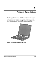
Notebook Evo N160 Series of Personal Computers offers advanced modularity, Intel Pentium III processors with 64-bit architecture, industry-leading Accelerated Graphics Port (AGP) implementation, and extensive multimedia support. Figure 1-1. Compaq Notebook Evo N160 Maintenance and Service Guide - Compaq Evo n160 | Maintenance and Service Guide Compaq Evo N160 Series - Page 7
drive 7 Integrated communication M=modem 0=none C=modem/NIC combination card 8 RAM 12=128 MB 9 Battery cells / type L=8 cells, Lithium ion (Li ion) 10 Operating system 8=Windows 98 2=Windows 2000 11 SKU# All computer models use configuration code KHYZ. 1-2 Maintenance and Service - Compaq Evo n160 | Maintenance and Service Guide Compaq Evo N160 Series - Page 8
Product Description Table 1-1 Compaq Notebook Evo N160 Models and Model Naming Conventions (Continued) 123 4 5 6 7 8 9 10 11 N16 P 100 X4 20 V C 12 L 8 Arabic 470024- (NAFTA) Korea 470024-050 Taiwan 470023-982 Latin America 470024-055 470024-065 (NAFTA) Maintenance and Service Guide 1-3 - Compaq Evo n160 | Maintenance and Service Guide Compaq Evo N160 Series - Page 9
Product Description Table 1-1 Compaq Notebook Evo N160 Models and Model Naming Conventions (Continued) N16 P 100 X4 20 V C 12 L 2 Arabic 470024-098 Latin America 470024- United Kingdom 470024-118 Korea 470024-052 United States 470023-989 470024-074 (NAFTA) 1-4 Maintenance and Service Guide - Compaq Evo n160 | Maintenance and Service Guide Compaq Evo N160 Series - Page 10
Product Description Table 1-1 Compaq Notebook Evo N160 Models and Model Naming Conventions (Continued) N16 C 933 X4 15 V C 12 L 8 Australia 470024-079 The Netherlands 470024 -034 470024-041 Korea 470024-039 N16 C 933 X4 15 V 0 12 L 8 European 470024-080 Maintenance and Service Guide 1-5 - Compaq Evo n160 | Maintenance and Service Guide Compaq Evo N160 Series - Page 11
Product Description Table 1-1 Compaq Notebook Evo N160 Models and Model Naming Conventions (Continued) N16 C 933 X4 15 V C 12 L 2 France 470024-049 Norway 470024-066 United Kingdom 470024-025 Israel 470024-009 United States 470023-997 Italy 470024-010 1-6 Maintenance and Service Guide - Compaq Evo n160 | Maintenance and Service Guide Compaq Evo N160 Series - Page 12
Product Description Table 1-1 Compaq Notebook Evo N160 Models and Model Naming Conventions (Continued) N16 C 933 X3 10 D C 12 L 2 France 470024-005 Swedish / Finnish 470024 -040 Italy 470024-011 Taiwan 470023-994 Spain 470024-018 Hong Kong 470023-993 Maintenance and Service Guide 1-7 - Compaq Evo n160 | Maintenance and Service Guide Compaq Evo N160 Series - Page 13
card (NIC) integrated on system board, with mini PCI V.90 modem I Support for one Type II PC Card slot with support for both 32-bit CardBus and 16-bit PC Cards I External AC adapter with power cord I 8-cell Lithium ion (Li ion) battery pack I 48-, 30-, 20-, 15-, or 10-GB high-capacity hard drive - Compaq Evo n160 | Maintenance and Service Guide Compaq Evo N160 Series - Page 14
❏ RJ-11 modem ❏ Universal Serial Bus ❏ S-Video ❏ Parallel devices ❏ External monitor ❏ 1394 digital devices ❏ AC power ❏ Stereo line out/headphone ❏ Mono microphone ❏ QuickDock Port Replicator I Stereo speakers providing Compaq Premier·Sound™ 16-bit stereo sound Maintenance and Service Guide 1-9 - Compaq Evo n160 | Maintenance and Service Guide Compaq Evo N160 Series - Page 15
"). 3. Wait approximately five minutes. 4. Replace the RTC battery and reassemble the computer. 5. Connect AC power to the computer. Do not reinsert any battery packs at this time. 6. Turn on the computer. All passwords and all CMOS settings have been cleared. 1-10 Maintenance and Service Guide - Compaq Evo n160 | Maintenance and Service Guide Compaq Evo N160 Series - Page 16
Product Description 1.3 Power Management The computer comes with power management features that extend battery operating time and conserve power. The computer supports the following power management features: I Standby I Hibernation I Setting customization by the user I Hotkeys for setting level of - Compaq Evo n160 | Maintenance and Service Guide Compaq Evo N160 Series - Page 17
Product Description 1.4 Computer External Components The external components on the front and right side of the computer are shown in Figure 1-2 and described in Table 1-1. . Figure 1-2. Front and Right Side Components 1-12 Maintenance and Service Guide - Compaq Evo n160 | Maintenance and Service Guide Compaq Evo N160 Series - Page 18
Product Description Table 1-1 Front and Right Side Components Item 1 2 3 Component Display release latch Stereo speakers Drive indicator light 4 Battery light 5 Battery bay 6 Modular media bay Function Opens the computer. Produce stereo sound. Turns on when the hard drive, CD-, or DVD-ROM - Compaq Evo n160 | Maintenance and Service Guide Compaq Evo N160 Series - Page 19
Product Description The computer rear panel and RJ-11 jack (internal modem models only) 3 USB connectors (2) 4 S-Video connector 5 Parallel connector 6 External monitor connector Function Connects the network cable external monitor or overhead projector. 1-14 Maintenance and Service Guide - Compaq Evo n160 | Maintenance and Service Guide Compaq Evo N160 Series - Page 20
jack 10 Mono microphone jack 11 Security cable slot 12 Vent 13 PC Card slot 14 PC Card eject button 15 Hard drive bay Function Connects IEEE 1394-compliant products, such as digital camcorders, video editing equipment, VCRs, cameras, and audio players. A 1394 firewire cable is required for - Compaq Evo n160 | Maintenance and Service Guide Compaq Evo N160 Series - Page 21
Product Description The keyboard components are shown in Figure 1-4 and described in Table 1-3. Figure 1-4. Keyboard Components 1-16 Maintenance and Service Guide - Compaq Evo n160 | Maintenance and Service Guide Compaq Evo N160 Series - Page 22
to perform preset hotkey functions. Displays Windows Start menu. Displays a menu when using a Microsoft application. The menu is the same one that is displayed by pressing the right mouse button. Move the cursor around the screen. Converts keys to numeric keypad. Maintenance and Service Guide 1-17 - Compaq Evo n160 | Maintenance and Service Guide Compaq Evo N160 Series - Page 23
Product Description The components on the top of the computer are shown in Figure 1-5 and described in Table 1-4. other flexible surface that may cover the vent area. Adjust the volume of the stereo speakers. Launches Windows Media Player to play MP3 music. 1-18 Maintenance and Service Guide - Compaq Evo n160 | Maintenance and Service Guide Compaq Evo N160 Series - Page 24
an external mouse. Scrolls the screen left, right, up, and down. Turns on when the hard drive, CD-, or DVD-ROM drive is accessed. On: A battery pack is charging. Blinking: A battery pack that is the only available power source has reached a low-battery condition. Maintenance and Service Guide 1-19 - Compaq Evo n160 | Maintenance and Service Guide Compaq Evo N160 Series - Page 25
Bottom Components Table 1-5 Bottom Components Item 1 Component Hard drive retention screw 2 Hard drive bay Function Secures the hard drive to the computer. Supports the removable primary hard drive. The hard drive is secured to the computer by one screw. 1-20 Maintenance and Service Guide - Compaq Evo n160 | Maintenance and Service Guide Compaq Evo N160 Series - Page 26
stereo sound. Identifies the computer; needed when you call Compaq customer support. Contains the Product Key, which may need to be entered before using some Windows operating systems. Accepts a 9- or 6-cell Lithium ion (li ion) battery pack. Releases the battery pack from the battery compartment - Compaq Evo n160 | Maintenance and Service Guide Compaq Evo N160 Series - Page 27
parts and features of the computer. Refer to Chapter 3, "Illustrated Parts Catalog," to identify replacement parts, and Chapter 5, "Removal and Replacement Procedures," for disassembly steps. The system board provides the following device connections: I Memory expansion board I Hard drive I Display - Compaq Evo n160 | Maintenance and Service Guide Compaq Evo N160 Series - Page 28
the system BIOS to diagnose and solve minor problems. I drives, power management, and password settings. To run PSU, press the F10 key during system startup. When the main screen displays, use the keyboard and arrow keys to move around the menus and make selections. Maintenance and Service Guide - Compaq Evo n160 | Maintenance and Service Guide Compaq Evo N160 Series - Page 29
troubleshooting No power, part 1 No power, part 2 No power, part 3 No power, part 4 No video, part 1 No video, part 2 Nonfunctioning docking station No operating system (OS) loading No OS loading from hard drive, part 1 No OS loading from hard drive, part 2 No OS loading from hard drive, part - Compaq Evo n160 | Maintenance and Service Guide Compaq Evo N160 Series - Page 30
Begin Troubleshooting. N Is there power? Y Go to Section 2.2, No Power. N Beeps, LEDs, or error Messages? Y Check LED board, speaker connections. N Is there video? (no boot) Y Go to Section 2.6, No Video. N Is the OS loading? Go to Section 2.9, No OS Loading. Y N Is there sound? Y Go - Compaq Evo n160 | Maintenance and Service Guide Compaq Evo N160 Series - Page 31
Troubleshooting 2.2 No Power, Part 1 No Power (Power LED is off) Remove from docking station if applicable. N Power up on battery power? Y *Reset power. N Power up on battery power? Y Go to Section 2.3, No Power, Part 2.8, Nonfunctioning Docking Station. 2-4 Maintenance and Service Guide - Compaq Evo n160 | Maintenance and Service Guide Compaq Evo N160 Series - Page 32
socket and clean if necessary. Y Power on? N Done Check battery by recharging, moving it to another computer, or replacing it. N Power on? Y Replace power supply (if applicable). N Done Power on? Y Troubleshooting Go to Section 2.4, No Power, Part 3. Done Maintenance and Service Guide 2-5 - Compaq Evo n160 | Maintenance and Service Guide Compaq Evo N160 Series - Page 33
source. Y Power on? N N Power outlet active? Y Replace power cord. Y Power on? N Done Done Try different outlet. Done External Internal or external AC adapter? Replace external AC adapter. Internal Go to Section 2.5, No Power, Part 4. N Power on? Y Done 2-6 Maintenance and Service Guide - Compaq Evo n160 | Maintenance and Service Guide Compaq Evo N160 Series - Page 34
? Y Done Replace the following items, if applicable. Check computer operation after each replacement: 1. Internal DC-DC converter* 2. Internal AC adapter 3. Processor board* 4. System board* *Replace these items as a set to prevent shorting out among components. Maintenance and Service Guide 2-7 - Compaq Evo n160 | Maintenance and Service Guide Compaq Evo N160 Series - Page 35
. Test after each replacement. 1. Cable between notebook and computer display (if applicable) 2. Inverter board (if applicable) 3. Display 4. System board N Video OK? Y Try another display. Internal and external video OK? Y Replace system board. Done Done 2-8 Maintenance and Service Guide - Compaq Evo n160 | Maintenance and Service Guide Compaq Evo N160 Series - Page 36
Troubleshooting 2.7 No Video, Part 2 Continued from Section 2.6, No Video, Part 1. Remove notebook from docking station, if connected. Adjust display brightness. Check brightness of external monitor. N Video OK? Y Go to "A" in Section 2.6, No Video, Part 1. Y Video OK? N Check for notebook - Compaq Evo n160 | Maintenance and Service Guide Compaq Evo N160 Series - Page 37
notebook into docking station. Y Docking station operating? N Done Replace these docking station components one at a time. Check computer operation after each replacement. 1. Power supply 2. I/O board 3. Backplane board 4. Switch box 5. Docking motor mechanism 2-10 Maintenance and Service Guide - Compaq Evo n160 | Maintenance and Service Guide Compaq Evo N160 Series - Page 38
Troubleshooting 2.9 No Operating System (OS) Loading No OS loading* Reseat power cord in docking station and power outlet. No OS loading from hard drive, go to Section 2.10. No OS loading form diskette drive, go to Section 2.13. No OS loading from CD- or DVD-ROM drive, go to Section 2.14. No OS - Compaq Evo n160 | Maintenance and Service Guide Compaq Evo N160 Series - Page 39
Troubleshooting 2.10 No OS Loading from Hard Drive, Part 1 OS not loading from hard drive. Y Nonsystem disk message? N Reseat external hard drive. Go to Section 2.11, No OS Loading from Hard Drive, Part 2. Y OS loading? Done N N Boot from CD? Y Check the setup utility for correct booting - Compaq Evo n160 | Maintenance and Service Guide Compaq Evo N160 Series - Page 40
Troubleshooting 2.11 No OS Loading from Hard Drive, Part 2 Continued from Section 2.10, No OS Loading from Hard Drive, Part 1. N CD or diskette in drive? Y 1. Replace hard drive. 2. Replace system board. Reseat hard drive. Y Hard drive accessible? Done Remove diskette and reboot. N Run FDISK. - Compaq Evo n160 | Maintenance and Service Guide Compaq Evo N160 Series - Page 41
Troubleshooting 2.12 No OS Loading from Hard Drive, Part 3 Continued from Section 2.11, No OS Loading from Hard Drive, Part 2. N System files on hard drive? Y Install OS and reboot. Y Virus on hard drive? N Run SCANDISK and check for bad sectors. N Can bad sectors be fixed? Y Clean virus. Y OS - Compaq Evo n160 | Maintenance and Service Guide Compaq Evo N160 Series - Page 42
. Y Check diskette for system files. Try different diskette. Y Nonsystem disk error? 1. Replace diskette drive. 2. Replace system board. N Y OS loading? N Done Change boot priority using the setup utility. Go to Section 2.17, Nonfunctioning Device. Maintenance and Service Guide 2-15 - Compaq Evo n160 | Maintenance and Service Guide Compaq Evo N160 Series - Page 43
Troubleshooting 2.14 No OS Loading from CD- or DVD-ROM Drive Y N No OS loading from Disc CD- or in drive? DVD-ROM drive. N Bootable disc in drive from CD or DVD? N Done Y Reseat drive. Boots from CD or DVD? N N Section 1.2, Clearing a Password, for instructions. Go to Section 2.17, - Compaq Evo n160 | Maintenance and Service Guide Compaq Evo N160 Series - Page 44
Troubleshooting 2.15 No Audio, Part 1 Y No audio Turn up audio internally or externally. Audio? Done N Y Notebook in docking station (if applicable)? N Undock N Internal audio? Go to Section 2.16, No Audio, Part 2. Y Go to Section 2.16, No Audio, Part 2. Replace the following docking - Compaq Evo n160 | Maintenance and Service Guide Compaq Evo N160 Series - Page 45
Load drivers and set configuration in OS. Connect to external speaker. N Audio? Y Replace audio board and speaker connections in notebook, if applicable. Y Audio? N Done 1. Replace internal speakers. 2. Replace audio board, if applicable. 3. Replace system board. 2-18 Maintenance and Service - Compaq Evo n160 | Maintenance and Service Guide Compaq Evo N160 Series - Page 46
damage. Y Any physical device? N Fix or replace broken item. Reattach device. Close notebook, plug in power, and reboot. N Device boots properly? Y Possible bad hard drive. Replace drive. Possible bad NIC. Replace card. If integrated NIC, replace system board. Go to Section 2.9, No OS Loading - Compaq Evo n160 | Maintenance and Service Guide Compaq Evo N160 Series - Page 47
operating properly. Connect notebook to good external keyboard. N External device works? Y Replace system board. Reseat internal keyboard connector (if applicable). N OK? Y Replace internal keyboard or cable. Y Done OK? N Replace system board. Done 2-20 Maintenance and Service Guide - Compaq Evo n160 | Maintenance and Service Guide Compaq Evo N160 Series - Page 48
. Connect notebook to good external pointing device. N External device works? Y Replace system board. Reseat internal pointing device connector (if applicable). N Replace internal OK? pointing device or cable. Y Y Done OK? N Replace system board. Done Maintenance and Service Guide - Compaq Evo n160 | Maintenance and Service Guide Compaq Evo N160 Series - Page 49
to non-digital line. N N NIC/modem configured in OS? Reload drivers and reconfigure. Y N Y OK? Disconnect all power from the notebook and open. Reseat NIC/modem if applicable. Replace NIC/modem if applicable. Y OK? N Done Done Replace system board. 2-22 Maintenance and Service Guide - Compaq Evo n160 | Maintenance and Service Guide Compaq Evo N160 Series - Page 50
for spare part numbers and option part numbers. 3.1 Serial Number Location When ordering parts or requesting information, provide the computer serial number and model number located on the bottom of the computer (Figure 3-1). Figure 3-1. Serial Number Location Maintenance and Service Guide 3-1 - Compaq Evo n160 | Maintenance and Service Guide Compaq Evo N160 Series - Page 51
Illustrated Parts Catalog 3.2 Computer System Major Components p Figure 3-2. Computer System Major Components 3-2 Maintenance and Service Guide - Compaq Evo n160 | Maintenance and Service Guide Compaq Evo N160 Series - Page 52
: Switch cover Left hinge cover Right hinge cover Keyboard shield Left display support Right display support Disk cell RTC battery Hard drive bracket Hard drive shield Hard drive sleeve Memory expansion compartment cover Docking connector cover Keyboards Belgian Brazilian Danish French French - Compaq Evo n160 | Maintenance and Service Guide Compaq Evo N160 Series - Page 53
Illustrated Parts Catalog Computer System Major Components (continued) 3-4 Maintenance and Service Guide - Compaq Evo n160 | Maintenance and Service Guide Compaq Evo N160 Series - Page 54
I/O board Hard drives 48 GB 30 GB 20 GB 10 GB Spare Part Number 251367-001 252440-001 251348-001 251347-001 251346-001 251345-001 252439-001 252442-001 252441-001 260606-001 259488-001 259489-001 251368-001 251381-001 251359-001 251358-001 251357-001 251356-001 Maintenance and Service Guide 3-5 - Compaq Evo n160 | Maintenance and Service Guide Compaq Evo N160 Series - Page 55
Illustrated Parts Catalog Computer System Major Components (continued) 3-6 Maintenance and Service Guide - Compaq Evo n160 | Maintenance and Service Guide Compaq Evo N160 Series - Page 56
Table 3-1 Spare Parts: Computer System Major Components (Continued) Item 11a 11b 12 13 14 Description Speakers Left Right Base enclosure Battery packs 4.0 amp hour capacity 3.6 amp hour capacity Modular media bay device Diskette drive 24X Max CD-ROM drive 8X Max CD-RW drive DVD-ROM drive DVD-ROM - Compaq Evo n160 | Maintenance and Service Guide Compaq Evo N160 Series - Page 57
Display supports 4 Keyboard shield 5 Disk cell RTC battery 6 Docking connector cover Item 7 8 9 10 11 12 Description Memory expansion compartment cover Hard drive bracket Hard drive shield Hard drive sleeve PC Card slot space saver Modular media bay space saver 3-8 Maintenance and Service - Compaq Evo n160 | Maintenance and Service Guide Compaq Evo N160 Series - Page 58
GB 30 GB 20 GB 10 GB Modular media bay device Diskette drive 24X Max CD-ROM drive 8X Max CD-RW drive DVD-ROM drive DVD-ROM/CD-RW combination drive Spare Part Number 251359-001 251358-001 251357-001 251356-001 251349-001 221761-001 226745-001 198702-001 230217-001 Maintenance and Service Guide 3-9 - Compaq Evo n160 | Maintenance and Service Guide Compaq Evo N160 Series - Page 59
kit (includes the following screws and bushing guides; refer to Appendix C, "Screw Listing," for more information on screw specifications and usage.) 251366-001 I Torx T8 M2 × 7 I Torx T8 M2 × 5 I 7.0-mm bushing guide I Phillips M1 × 6 I Phillips M2 × 6.5 3-10 Maintenance and Service Guide - Compaq Evo n160 | Maintenance and Service Guide Compaq Evo N160 Series - Page 60
Chinese International Italian Japanese 198723-011 198723-AA1 198723-B31 198723-061 198723-291 Description Memory expansion boards 512 MB 256 MB 128 MB 64 MB External battery charger Spare Part Number 198713-001 198714-001 Swiss U.K. English U.S. English 174120-115 174120-031 174120-001 Korean - Compaq Evo n160 | Maintenance and Service Guide Compaq Evo N160 Series - Page 61
service. 4.1 Tools Required You will need the following tools to complete the removal and replacement procedures: I Magnetic screwdriver I Phillips P0 and P1 screwdrivers I Tool kit (includes connector removal tool, loopback plugs, and case utility tool) Maintenance and Service Guide 4-1 - Compaq Evo n160 | Maintenance and Service Guide Compaq Evo N160 Series - Page 62
plastic parts. Use care when handling the plastic parts. Apply pressure only at the points designated in the maintenance instructions. Cables or snagged by parts being removed or replaced. Handle flex cables with extreme care; these cables tear easily. Ä CAUTION: When servicing the computer, ensure - Compaq Evo n160 | Maintenance and Service Guide Compaq Evo N160 Series - Page 63
least one inch of shock-proof foam. I Avoid dropping drives from any height onto any surface. I After removing a hard drive, CD-ROM drive, or a diskette drive, place it into a static-proof bag. I Avoid exposing a hard drive to products that have magnetic fields, such as monitors or speakers. I Avoid - Compaq Evo n160 | Maintenance and Service Guide Compaq Evo N160 Series - Page 64
electrostatic-sensitive parts in their containers until the parts arrive at static-free workstations. I Place items on a grounded surface before removing items from their containers. I Always be properly grounded when touching a sensitive component or assembly. 4-4 Maintenance and Service Guide - Compaq Evo n160 | Maintenance and Service Guide Compaq Evo N160 Series - Page 65
Replacement Preliminaries I Place reusable electrostatic-sensitive parts grounded tools and equipment. I Use conductive field service tools, such as cutters, screwdrivers, and vacuums. aids and Styrofoam. I Handle electrostatic-sensitive components, parts, and assemblies by the case or PCM laminate. - Compaq Evo n160 | Maintenance and Service Guide Compaq Evo N160 Series - Page 66
Replacement Preliminaries 4.7 Grounding Equipment and Methods Grounding equipment must include either a wrist strap or a foot strap at a grounded workstation. I When seated, wear a wrist strap connected to a grounded system or floor mats with hard tie to ground I Field service kits I Static awareness - Compaq Evo n160 | Maintenance and Service Guide Compaq Evo N160 Series - Page 67
Removal and Replacement Preliminaries I Nonconductive plastic bags, 000 V Packing PCBs in foam-lined box 21,000 V 11,000 V 5,000 V ✎ A product can be degraded by as little as 700 volts. Table 4-2 lists the shielding protection provided by 500 V 5,000 V Maintenance and Service Guide 4-7 - Compaq Evo n160 | Maintenance and Service Guide Compaq Evo N160 Series - Page 68
disassembly. There are 41 screws, in 10 different sizes, that must be removed and replaced when servicing the computer. Make special note of each screw size and location during removal and replacement. Refer to Appendix C, "Screw Listing," for detailed information on screw sizes, locations, and - Compaq Evo n160 | Maintenance and Service Guide Compaq Evo N160 Series - Page 69
Removal and Replacement Procedures 5.1 Serial Number Report the computer serial number to Compaq when requesting information or ordering spare parts. The serial number is located on the bottom of the computer (Figure 5-1). Figure 5-1. Serial Number Location 5-2 Maintenance and Service Guide - Compaq Evo n160 | Maintenance and Service Guide Compaq Evo N160 Series - Page 70
device Memory expansion board Computer feet Switch cover Keyboard Fan assembly Processor Display Top cover Speaker assembly Disk cell RTC battery Mini PCI communications board Sub I/O board System board # of Screws Removed 0 0 1 hard drive retention screw 4 securing hard drive to hard drive sleeve - Compaq Evo n160 | Maintenance and Service Guide Compaq Evo N160 Series - Page 71
release latch toward the back of the computer 1 (Figure 5-2). c. Use the notch in the battery bezel to slide the battery pack to the left 2. d. Remove the battery pack. Figure 5-2. Removing the Battery Pack Reverse the above procedure to install the battery pack. 5-4 Maintenance and Service Guide - Compaq Evo n160 | Maintenance and Service Guide Compaq Evo N160 Series - Page 72
8 screw 1 (Figure 5-3). c. Use a thin flat tool (screwdriver, case utility tool) to slide the front edge of the hard drive sleeve to the right 2. d. Remove the hard drive. Figure 5-3. Removing the Hard Drive Reverse the above procedure to install the hard drive. Maintenance and Service Guide 5-5 - Compaq Evo n160 | Maintenance and Service Guide Compaq Evo N160 Series - Page 73
of the hard drive shield 3 when removing the hard drive from the hard drive sleeve. ✎ The hard drive sleeve and shield are included in the Plastics and Hardware Kit (spare part number 251365-001). Figure 5-4. Removing the Hard Drive from the Hard Drive Sleeve 5-6 Maintenance and Service Guide - Compaq Evo n160 | Maintenance and Service Guide Compaq Evo N160 Series - Page 74
Removal and Replacement Procedures 5. Remove a modular media bay device by following these steps: a. Turn the computer bottom side up with the . Figure 5-5. Removing a Modular Media Bay Device Reverse the above procedure to install a modular media bay device. Maintenance and Service Guide 5-7 - Compaq Evo n160 | Maintenance and Service Guide Compaq Evo N160 Series - Page 75
the back of the computer 2. 5. Remove the memory expansion compartment cover 3. ✎ The memory expansion compartment cover is included in the Plastics and Hardware Kit (spare part number 251365-001). Figure 5-6. Removing the Memory Expansion Compartment Cover 5-8 Maintenance and Service Guide - Compaq Evo n160 | Maintenance and Service Guide Compaq Evo N160 Series - Page 76
1 (Figure 5-7). 7. The board tilts up at a 45-degree angle. 8. Remove the board by pulling it away from the connector at a 45-degree angle 2. Figure 5-7. Removing a Memory Expansion Board Reverse the above procedure to install a memory expansion board. Maintenance and Service Guide 5-9 - Compaq Evo n160 | Maintenance and Service Guide Compaq Evo N160 Series - Page 77
5.5 Computer Feet The computer feet are adhesive-backed rubber pads. The computer feet are included in the Plastics and Hardware Kit (spare part number 251365-001). Refer to Figure 5-8 for computer feet locations. Figure 5-8. Replacing the Computer Feet 5-10 Maintenance and Service Guide - Compaq Evo n160 | Maintenance and Service Guide Compaq Evo N160 Series - Page 78
Removal and Replacement Procedures 5.6 Switch Cover ✎ The switch cover is included in the Plastics and Hardware Kit (spare part number 251365-001). 1. Prepare the computer for disassembly (Section 5.3). 2. Turn the 5. Open the computer as far as it will open. Maintenance and Service Guide 5-11 - Compaq Evo n160 | Maintenance and Service Guide Compaq Evo N160 Series - Page 79
Removal and Replacement Procedures 6. Press down and hold the Esc key 1 (Figure 5-10). 7. Use a small straight edge tool (screwdriver or tweezers) the switch cover 3. Figure 5-10. Removing the Switch Cover Reverse the above procedure to install the switch cover. 5-12 Maintenance and Service Guide - Compaq Evo n160 | Maintenance and Service Guide Compaq Evo N160 Series - Page 80
Removal and Replacement Procedures 5.7 Keyboard Keyboards Spare Part Number Information Belgian Brazilian Danish French French Canadian German International Italian Japanese the computer for disassembly (Section 5.3). 2. Remove the switch cover (Section 5.6). Maintenance and Service Guide 5-13 - Compaq Evo n160 | Maintenance and Service Guide Compaq Evo N160 Series - Page 81
Removal and Replacement Procedures 3. Lift up the back edge of the keyboard and swing it up and forward until it rests on the top cover (Figure 5-11). fi Figure 5-11. Releasing the Keyboard 5-14 Maintenance and Service Guide - Compaq Evo n160 | Maintenance and Service Guide Compaq Evo N160 Series - Page 82
Removal and Replacement Procedures 4. Remove the two silver M2 × 5 screws 1 that secure the keyboard shield to the base enclosure (Figure 5-12). 5. Remove Cable 7. Remove the keyboard. Reverse the above procedure to install the keyboard and keyboard shield. Maintenance and Service Guide 5-15 - Compaq Evo n160 | Maintenance and Service Guide Compaq Evo N160 Series - Page 83
5.8 Fan Assembly Fan Assembly Spare Part Number Information Fan (includes heat sink) 251367-001 1. Prepare the computer for disassembly (Section 5.3). 2. Remove the switch cover (Section 5.6). 3. Remove the keyboard and keyboard shield (Section 5.7). 5-16 Maintenance and Service Guide - Compaq Evo n160 | Maintenance and Service Guide Compaq Evo N160 Series - Page 84
Removal and Replacement Procedures 4. Disconnect the fan cable from the system board 1 (Figure 5-13). 5. Loosen the four silver M2.5 × 18 shoulder screws 2 that secure the fan 13. Removing the Fan Assembly Reverse the above procedure to install the fan assembly. Maintenance and Service Guide 5-17 - Compaq Evo n160 | Maintenance and Service Guide Compaq Evo N160 Series - Page 85
Removal and Replacement Procedures 5.9 Processor Processors Spare Part Number Information Intel Pentium III 1.2 GHz Intel Pentium III 1.133 GHz Intel a. Switch cover (Section 5.6) b. Keyboard and keyboard shield (Section 5.7) c. Fan assembly (Section 5.8) 5-18 Maintenance and Service Guide - Compaq Evo n160 | Maintenance and Service Guide Compaq Evo N160 Series - Page 86
Removal and Replacement Procedures 2. Use a flat-blade screwdriver to turn the processor locking screw 1 one-half turn counterclockwise (Figure 5-14). 3. lower left corner. Figure 5-14. Removing the Processor Reverse the above procedure to install the processor. Maintenance and Service Guide 5-19 - Compaq Evo n160 | Maintenance and Service Guide Compaq Evo N160 Series - Page 87
Removal and Replacement Procedures 5.10 Display Displays Spare Part Number Information 14.1-inch, SXGA, CTFT 14.1-inch, XGA, CTFT 13.3-inch, XGA, CTFT 260604-001 5.6). 3. Close the computer. 4. Turn the computer top side up with the rear panel facing you. 5-20 Maintenance and Service Guide - Compaq Evo n160 | Maintenance and Service Guide Compaq Evo N160 Series - Page 88
Removal and Replacement Procedures 5. Insert a small straight edge tool (screwdriver or tweezers) spare part number 251365-001). 8. Remove the four silver M2 × 10.5 screws 5 from the computer rear panel. Figure 5-15. Removing the Hinge Covers and Display Screws Maintenance and Service Guide 5- - Compaq Evo n160 | Maintenance and Service Guide Compaq Evo N160 Series - Page 89
it forward until it rests on the top cover. 12. Disconnect the display inverter 1 and video cables 2 (Figure 5-16). ✎ When installing the display, route the display video cable through the clip 3 in the top cover. Figure 5-16. Disconnecting the Display Cables 5-22 Maintenance and Service Guide - Compaq Evo n160 | Maintenance and Service Guide Compaq Evo N160 Series - Page 90
to lose this bracket when replacing the display. 14. Remove the silver M2 × 10.5 screw 3 that secures the right display hinge. 15. Lift the display straight up to remove it 4. Figure 5-17. Removing the Display Reverse the above procedure to install the display. Maintenance and Service Guide 5-23 - Compaq Evo n160 | Maintenance and Service Guide Compaq Evo N160 Series - Page 91
Removal and Replacement Procedures 5.11 Top Cover Top Cover Spare Part Number Information Top cover (includes TouchPad and TouchPad buttons shield (Section 5.7) c. Display (Section 5.10) 2. Turn the computer bottom side up with the rear panel facing you. 5-24 Maintenance and Service Guide - Compaq Evo n160 | Maintenance and Service Guide Compaq Evo N160 Series - Page 92
Removal and Replacement Procedures 3. Remove the eight black M2 × 9 screws 1 that secure the top cover to the base enclosure (Figure 5-18). 4. Open the parallel Figure 5-18. Removing the Top Cover Screws 6. Turn the computer top side up with the front facing you. Maintenance and Service Guide 5-25 - Compaq Evo n160 | Maintenance and Service Guide Compaq Evo N160 Series - Page 93
the TouchPad cable 2 from the system board (Figure 5-19). 8. Remove the two black M2 × 9 screws 3 and the silver M2 × 7 screw 4 that secures the top cover to the base enclosure. Figure 5-19. Disconnecting the TouchPad Cable and Removing the Top Cover Screws 5-26 Maintenance and Service Guide - Compaq Evo n160 | Maintenance and Service Guide Compaq Evo N160 Series - Page 94
Removal and Replacement Procedures 9. Lift the top cover straight up to remove it (Figure 5-20). Figure 5-20. Removing the Top Cover Reverse the above procedure to install the top cover. Maintenance and Service Guide 5-27 - Compaq Evo n160 | Maintenance and Service Guide Compaq Evo N160 Series - Page 95
Replacement Procedures 5.12 Speaker Assembly ✎ The left and right speakers are not interchangeable. The right speaker has a longer cable. Speaker Assembly Spare Part Keyboard and keyboard shield (Section 5.7) c. Display (Section 5.10) d. Top cover (Section 5.11) 5-28 Maintenance and Service Guide - Compaq Evo n160 | Maintenance and Service Guide Compaq Evo N160 Series - Page 96
the system board (Figure 5-21). 3. Remove the gold M2 × 5 screws 2 that secure the speaker assemblies to the base enclosure. 4. Remove the speaker assemblies 3. Figure 5-21. Removing the Speaker Assemblies Reverse the above procedure to install the speaker assemblies. Maintenance and Service Guide - Compaq Evo n160 | Maintenance and Service Guide Compaq Evo N160 Series - Page 97
5.10) d. Top cover (Sevtion 5-11) 2. Lift up the back edge of the RTC battery and remove it from its socket on the system board (Figure 5-22). Figure 5-22. Removing the Disk Cell RTC Battery Reverse the above procedure to install the disk cell RTC battery. 5-30 Maintenance and Service Guide - Compaq Evo n160 | Maintenance and Service Guide Compaq Evo N160 Series - Page 98
Removal and Replacement Procedures 5.14 Mini PCI Communications Board Mini PCI Communications Boards Spare Part Number Information Mini PCI cover (Section 5.6) b. Keyboard and keyboard shield (Section 5.7) c. Display (Section 5.10) d. Top cover (Section 5.11) Maintenance and Service Guide 5-31 - Compaq Evo n160 | Maintenance and Service Guide Compaq Evo N160 Series - Page 99
Removal and Replacement Procedures 2. Disconnect the communications cable from the mini PCI communications board 1 (Figure 5-23). 3. Spread the retaining the Mini PCI Communications Board Reverse the above procedure to install the mini PCI communications board. 5-32 Maintenance and Service Guide - Compaq Evo n160 | Maintenance and Service Guide Compaq Evo N160 Series - Page 100
and Replacement Procedures 5.15 Sub I/O Board Sub I/O Board Spare Part Number Information Sub I/O board 251381-001 1. Prepare the computer for disassembly (Section 5.3) and remove the following components: a. Switch cover (Section 5.6) b. Keyboard and keyboard shield (Section 5.7) c. Display - Compaq Evo n160 | Maintenance and Service Guide Compaq Evo N160 Series - Page 101
× 6.5 screw also captures the modem/NIC ground cable 3 (Figure 5-24). 3. Remove the right display support 4. ✎ The right display support is included in the Plastics and Hardware Kit (spare part number 251365-001). Figure 5-24. Removing the Right Display Support 5-34 Maintenance and Service Guide - Compaq Evo n160 | Maintenance and Service Guide Compaq Evo N160 Series - Page 102
sub I/O board 2 until it clears the base enclosure. 6. Slide the sub I/O board to the right 3 to disconnect it from the system board. Figure 5-25. Removing the Sub I/O Board 7. Remove the sub I/O board. Reverse the above procedure to install the sub I/O board. Maintenance and Service Guide 5-35 - Compaq Evo n160 | Maintenance and Service Guide Compaq Evo N160 Series - Page 103
and Replacement Procedures 5.16 System Board System Board Spare Part Number Information System board 251368-001 1. Prepare the computer for disassembly (Section 5.3) and remove the following components: a. Switch cover (Section 5.6) b. Keyboard and keyboard shield (Section 5.7) c. Display - Compaq Evo n160 | Maintenance and Service Guide Compaq Evo N160 Series - Page 104
Figure 5-26). 3. Disconnect the speaker assembly cables 2 from the system board. 4. Remove the two silver M2 × 6.5 screws 3 that secure the hard drive bracket to the base enclosure. 5. Remove the hard drive bracket 4. Figure 5-26. Removing the Hard Drive Bracket Maintenance and Service Guide 5-37 - Compaq Evo n160 | Maintenance and Service Guide Compaq Evo N160 Series - Page 105
✎ The left display support is included in the Plastics and Hardware Kit (spare part number 251365-001). 8. Remove the silver M2 × 5 screw 3 that secures the system board to the base enclosure. Figure 5-27. Removing the Left Display Support and System Board Screw 5-38 Maintenance and Service Guide - Compaq Evo n160 | Maintenance and Service Guide Compaq Evo N160 Series - Page 106
from the system board: I Memory expansion board (Section 5.4) I Fan assembly (Section 5.8) I Processor (Section 5.9) I Disk cell RTC battery (Section 5.13) I Mini PCI communications board (Section 5.14) Reverse the above procedure to install the system board. Maintenance and Service Guide 5-39 - Compaq Evo n160 | Maintenance and Service Guide Compaq Evo N160 Series - Page 107
This chapter provides physical and performance specifications. Table 6-1 Computer Dimensions Height Width Depth 1.29 in 12.80 in 10.37 in 3.28 cm 32.51 Altitude (unpressurized) Operating Nonoperating 0 to 10,000 ft 0 to 30,000 ft 0 to 3,048 m 0 to 9,144 m Maintenance and Service Guide 6-1 - Compaq Evo n160 | Maintenance and Service Guide Compaq Evo N160 Series - Page 108
sine 0.5 G zero-to-peak, 10-500 Hz, 0.25-oct/min sweep rate 1.0 G zero-to-peak, 10-500 Hz, 0.25-oct/min sweep rate ✎ Applicable product safety standards specify thermal limits for plastic surfaces. The computer operates well within this range of temperatures. 6-2 Maintenance and Service Guide - Compaq Evo n160 | Maintenance and Service Guide Compaq Evo N160 Series - Page 109
Pitch Format Configuration Backlight Character display Refresh Total power consumption 8.46 in 11.22 in 14.10 in Up to 16.8 million 150:1 120 nits typical 1024 × 768 RGB vertical stripe Edge lit 80 × 25 60 Hz 4.2 W 21.40 cm 28.50 cm 35.81 cm 0.264 × 0.264 mm Maintenance and Service Guide 6-3 - Compaq Evo n160 | Maintenance and Service Guide Compaq Evo N160 Series - Page 110
Pitch Format Configuration Backlight Character display Refresh Total power consumption 7.98 in 10.64 in 13.3 in Up to 16.8 million 150:1 120 nits typical 1024 × 768 RGB vertical stripe Edge lit 80 × 25 60 Hz 4.0 W 20.28 cm 27.03 cm 33.79 cm 0.264 × 0.264 mm 6-4 Maintenance and Service Guide - Compaq Evo n160 | Maintenance and Service Guide Compaq Evo N160 Series - Page 111
per track 22,784 16 63 16,383 16 63 16,683 16 63 11 GB = 1,000,000,000 bytes. 2System capability may differ. 3Actual drive specifications may differ slightly. Certain restrictions and exclusions apply. Consult the Compaq Customer Support Center for details. Maintenance and Service Guide 6-5 - Compaq Evo n160 | Maintenance and Service Guide Compaq Evo N160 Series - Page 112
Specifications Table 6-3 Hard Drives (Continued) 30.0 GB 20.0 GB 15.0 GB . 2System capability may differ. 3Actual drive specifications may differ slightly. Certain restrictions and exclusions apply. Consult the Compaq Customer Support Center for details. 6-6 Maintenance and Service Guide - Compaq Evo n160 | Maintenance and Service Guide Compaq Evo N160 Series - Page 113
Specifications Table 6-4 Diskette Drive Diskette size Light Height Bytes per sector Sectors per track High density Low density Tracks per side High density Low density Read/write heads Average seek times Track-to-track (high/low) Average (high/low) Settling time Latency average 3.5 inch On system - Compaq Evo n160 | Maintenance and Service Guide Compaq Evo N160 Series - Page 114
Specifications Table 6-5 CD-ROM Drive Applicable disk Center hole diameter Disk Form 1 and 2) CD-I ready (Mode 2, Form 1 and 2) CD-R (read only) CD Plus Photo CD (single/multisession) CD-Extra Video CD CD-WO (fixed packets only) CD-Bridge .59 in 1.5 cm 12 cm, 8 cm 1.2 mm 1.6 µm < 150 ms < 300 - Compaq Evo n160 | Maintenance and Service Guide Compaq Evo N160 Series - Page 115
Specifications Table 6-6 DVD-ROM Drive Applicable disk Center hole diameter Disk diameter Disk thickness Track pitch Access time Random Full stroke Audio output level /s at 1X CD rate) 10,800 KB/s (1352 KB/s at 1X DVD rate) 16.6 MB/s < 12 seconds < 3 seconds Maintenance and Service Guide 6-9 - Compaq Evo n160 | Maintenance and Service Guide Compaq Evo N160 Series - Page 116
Specifications Table 6-7 CD-RW Drive Center hole diameter Disk diameter Disk thickness Track pitch Access time Random Full stroke Audio output level Cache < 225 ms Line-out, 0.7 Vrms 128 KB/s minimum 150 KB/s 5,520 KB/s 16.6 MB/s < 15 seconds < 6 seconds 6-10 Maintenance and Service Guide - Compaq Evo n160 | Maintenance and Service Guide Compaq Evo N160 Series - Page 117
Specifications Table 6-8 AC Adapter 1.3 A RMS 47 to 63 Hz nominal 4/50 kV Table 6-9 8-cell, Li ion Battery Pack Dimensions Length Width Depth Weight Energy Voltage Amp-hour capacity Watt-hour capacity Temperature Operating Nonoperating 140°F 0 to 42°C 0 to 60°C Maintenance and Service Guide 6-11 - Compaq Evo n160 | Maintenance and Service Guide Compaq Evo N160 Series - Page 118
Specifications Table 6-10 System DMA Hardware DMA System Function DMA0 Available for audio DMA1 Entertainment audio (default; alternate = DMA0, DMA3, none) DMA2 Diskette drive DMA3 ECP parallel port LPT1 (default; alternate = DMA0, none) DMA4 DMA controller cascading (not available) - Compaq Evo n160 | Maintenance and Service Guide Compaq Evo N160 Series - Page 119
use IRQ12 Internal point stick or external mouse IRQ13 Coprocessor (not available to any peripheral) IRQ14 IDE interface (hard drive and optical drive) IRQ15 System use ✎ PC Cards may assert IRQ3, IRQ4, IRQ5, IRQ7, IRQ9, IRQ10, IRQ11, or IRQ15. Either the infrared or the serial port may - Compaq Evo n160 | Maintenance and Service Guide Compaq Evo N160 Series - Page 120
Specifications Table 6-12 System I/O Addresses I/O Address (hex) 000 - 00F 010 - 01F 020 - 021 022 - 024 025 - 03F 02E - 02F 040 - 05F 044 - 05f 060 061 062 - 063 064 065 - 06F 070 - 071 072 - 07F 080 - 08F 090 - 091 092 093 - 09F 0A0 - 0A1 System no. 2 6-14 Maintenance and Service Guide - Compaq Evo n160 | Maintenance and Service Guide Compaq Evo N160 Series - Page 121
Specifications Table 6-12 System I/O Addresses (Continued) I/O Address (hex) 0A2 - 0BF 0C0 - 0DF 0E0 - 0EF 0F0 - 0F1 0F2 - 0FF 100 - 16F 170 - 177 178 - 1EF 1F0 - 1F7 1F8 - 200 201 202 - 21F 220 - 22F 230 - 26D 26E - 26 278 - 27F 280 - 2AB 2A0 - 2A7 2A8 - 2E7 2E8 - 2EF System Service Guide 6-15 - Compaq Evo n160 | Maintenance and Service Guide Compaq Evo N160 Series - Page 122
- 3FF CF8 - CFB CFC - CFF System Function (shipping configuration) Unused Infrared port Unused Unused Secondary diskette drive controller Parallel port (LPT1/default) Unused FM synthesizer - OPL3 Unused VGA Reserved (parallel port/no EPP support) VGA PC Card controller in CPU Unused Internal modem - Compaq Evo n160 | Maintenance and Service Guide Compaq Evo N160 Series - Page 123
- 047FFFFF 04800000 - 07FFFFFF 08000000 - 080FFFFF 08200000 - FFFEFFFF FFFF0000 - FFFFFFFF System Function Base memory Video memory Video BIOS Unused System BIOS Extended memory Super extended memory Unused Video memory (direct access) Unused System BIOS Maintenance and Service Guide 6-17 - Compaq Evo n160 | Maintenance and Service Guide Compaq Evo N160 Series - Page 124
A Connector Pin Assignments Table A-1 RJ-45 Network Interface Pin Signal 1 Transmit + 2 Transmit - 3 Receive + 4 Unused 13 5 7 2468 Pin Signal 5 Unused 6 Receive - 7 Unused 8 Unused Maintenance and Service Guide A-1 - Compaq Evo n160 | Maintenance and Service Guide Compaq Evo N160 Series - Page 125
Connector Pin Assignments Table A-2 RJ-11 Modem Pin Signal 1 Unused 2 Tip 3 Ring Pin Signal 4 Unused 5 Unused 6 Unused Table A-3 Universal Serial Bus Pin Signal 1 +5 VDC 2 Data - A-2 Pin Signal 3 Data + 4 Ground Maintenance and Service Guide - Compaq Evo n160 | Maintenance and Service Guide Compaq Evo N160 Series - Page 126
Connector Pin Assignments Table A-4 S-Video Pin Signal 1 Ground (Y) 2 Ground (C) Pin Signal 3 Y-Luminance (Intensity) 4 C-Chrominance (Color) Maintenance and Service Guide A-3 - Compaq Evo n160 | Maintenance and Service Guide Compaq Evo N160 Series - Page 127
13 14 15 16 17 18-25 Signal Acknowledge* Busy Paper out Select Auto line feed* Error* Initialize printer* Select in* Signal ground A-4 Maintenance and Service Guide - Compaq Evo n160 | Maintenance and Service Guide Compaq Evo N160 Series - Page 128
10 5 Pin Signal 9 +5 VDC 10 Ground 11 Monitor detect 12 DDC 2B data 13 Horizontal sync 14 Vertical sync 15 DDC 2B clock Maintenance and Service Guide A-5 - Compaq Evo n160 | Maintenance and Service Guide Compaq Evo N160 Series - Page 129
Connector Pin Assignments Table A-7 Stereo Speaker/Headphone Pin Signal 1 Audio out 1 2 Pin Signal 2 Ground Table A-8 Microphone Pin Signal 1 Audio in 1 2 Pin Signal 2 Ground A-6 Maintenance and Service Guide - Compaq Evo n160 | Maintenance and Service Guide Compaq Evo N160 Series - Page 130
's wide range input feature permits it to operate cord set requirements, contact a Compaq authorized reseller or service provider. General Requirements The requirements or 250 volts AC, as required by each country's power system. I The appliance coupler must meet the mechanical configuration of - Compaq Evo n160 | Maintenance and Service Guide Compaq Evo N160 Series - Page 131
Power Cord Set Requirements Country-Specific Requirements 3-Conductor Power Cord Set Requirements Country Australia Austria Belgium Canada Denmark Finland France Germany Italy mark of the agency responsible for evaluation in the country where it will be used. B-2 Maintenance and Service Guide - Compaq Evo n160 | Maintenance and Service Guide Compaq Evo N160 Series - Page 132
or VCTF, 3-conductor, 1.00mm2 conductor size. The wall plug must be a two-pole grounding type with a Japanese Industrial Standard C8303 (7A, 125V) configuration. Maintenance and Service Guide B-3 - Compaq Evo n160 | Maintenance and Service Guide Compaq Evo N160 Series - Page 133
available in the Miscellaneous Screw Kit, spare part number 251366-001. Table C-1 Phillips M3 × 8.0 Screw Head Color Qty Length Thread Width Silver 1 8.0 mm 3.0 mm 6.0 mm Where used: One screw that secures the hard drive to the computer (documented in Section 5.3) Maintenance and Service Guide C-1 - Compaq Evo n160 | Maintenance and Service Guide Compaq Evo N160 Series - Page 134
Table C-2 Phillips M3.0 × 4.0 Screw Head Color Qty Length Thread Width Black 4 4.0 mm 3.0 mm 6.0 mm Where used: Four screws that secure the hard drive to the hard drive sleeve (documented in Section 5.3) C-2 Maintenance and Service Guide - Compaq Evo n160 | Maintenance and Service Guide Compaq Evo N160 Series - Page 135
Table C-3 Phillips M2.0 × 5.0 Screw Head Color Qty Length Thread Width Silver 4 5.0 mm 2.0 mm 5.0 mm Where used: One screw that secures the memory expansion compartment cover to the base enclosure (documented in Section 5.4) Maintenance and Service Guide C-3 - Compaq Evo n160 | Maintenance and Service Guide Compaq Evo N160 Series - Page 136
Table C-3 Phillips M2.0 × 5.0 Screw (Continued) Head Color Qty Length Thread Width Silver 4 5.0 mm 2.0 mm 5.0 mm Where used: Two screws that secure the keyboard shield to the top cover (documented in Section 5.7) C-4 Maintenance and Service Guide - Compaq Evo n160 | Maintenance and Service Guide Compaq Evo N160 Series - Page 137
Table C-3 Phillips M2.0 × 5.0 Screw (Continued) Head Color Qty Length Thread Width Silver 4 5.0 mm 2.0 mm 5.0 mm Where used: One screw that secures the system board to the base enclosure (documented in Section 5.16) Maintenance and Service Guide C-5 - Compaq Evo n160 | Maintenance and Service Guide Compaq Evo N160 Series - Page 138
Table C-4 Phillips M2.0 × 9.0 Screw Head Color Qty Length Thread Width Black 15 9.0 mm 2.0 mm 5.0 mm Where used: Two screws that secure the switch cover to the base enclosure memory expansion compartment cover to the base enclosure (documented in Section 5.6) C-6 Maintenance and Service Guide - Compaq Evo n160 | Maintenance and Service Guide Compaq Evo N160 Series - Page 139
Table C-4 Phillips M2.0 × 9.0 Screw (Continued) Head Color Qty Length Thread Width Black 15 9.0 mm 2.0 mm 5.0 mm Where used: Eight screws that secure the top cover to the base enclosure (documented in Section 5.11) Maintenance and Service Guide C-7 - Compaq Evo n160 | Maintenance and Service Guide Compaq Evo N160 Series - Page 140
Table C-4 Phillips M2.0 × 9.0 Screw (Continued) Head Color Qty Length Thread Width Black 15 9.0 mm 2.0 mm 5.0 mm Where used: Two screws that secure the top cover to the base enclosure (documented in Section 5.11) C-8 Maintenance and Service Guide - Compaq Evo n160 | Maintenance and Service Guide Compaq Evo N160 Series - Page 141
Table C-4 Phillips M2.0 × 9.0 Screw (Continued) Head Color Qty Length Thread Width Black 15 9.0 mm 2.0 mm 5.0 mm Where used: One screw that secures the right display support to the base enclosure (documented in Section 5.15) Maintenance and Service Guide C-9 - Compaq Evo n160 | Maintenance and Service Guide Compaq Evo N160 Series - Page 142
Table C-4 Phillips M2.0 × 9.0 Screw (Continued) Head Color Qty Length Thread Width Black 15 9.0 mm 2.0 mm 5.0 mm Where used: Two screws that secure the left display support to the base enclosure (documented in Section 5.16) C-10 Maintenance and Service Guide - Compaq Evo n160 | Maintenance and Service Guide Compaq Evo N160 Series - Page 143
Table C-5 Phillips M2.0 × 10.5 Screw Head Color Qty Length Thread Width Silver 5 10.5 2.0 mm 5.0 mm Where used: Four screws that secure the display to the base enclosure through the rear panel (documented in Section 5.10) Maintenance and Service Guide C-11 - Compaq Evo n160 | Maintenance and Service Guide Compaq Evo N160 Series - Page 144
Table C-5 Phillips M2.0 × 10.5 Screw (Continued) Head Color Qty Length Thread Width Silver 5 10.5 2.0 mm 5.0 mm Where used: One screw that secures the display to the base enclosure through the right hinge (documented in Section 5.10) C-12 Maintenance and Service Guide - Compaq Evo n160 | Maintenance and Service Guide Compaq Evo N160 Series - Page 145
Table C-6 Phillips M2.0 × 12.0 Screw Head Color Qty Length Thread Width Black 1 12.0 mm 2.0 mm 5.0 mm Where used: One screw that secures the display to the base enclosure through the left hinge (documented in Section 5.10) Maintenance and Service Guide C-13 - Compaq Evo n160 | Maintenance and Service Guide Compaq Evo N160 Series - Page 146
Table C-7 Phillips M2.0 × 6.5 Screw Head Color Qty Length Thread Width Silver 5 6.5 mm 2.0 mm 5.0 mm Where used: One screw that secures the top cover to the base enclosure through the rear panel (documented in Section 5.11) C-14 Maintenance and Service Guide - Compaq Evo n160 | Maintenance and Service Guide Compaq Evo N160 Series - Page 147
Table C-7 Phillips M2.0 × 6.5 Screw (Continued) Head Color Qty Length Thread Width Silver 5 6.5 mm 2.0 mm 5.0 mm Where used: One screw that secures the top cover to the base enclosure (documented in Section 5.11) Maintenance and Service Guide C-15 - Compaq Evo n160 | Maintenance and Service Guide Compaq Evo N160 Series - Page 148
M2.0 × 6.5 Screw (Continued) Head Color Qty Length Thread Width Silver 5 6.5 mm 2.0 mm 5.0 mm Where used: One screw that secures the right display support and sub I/O board to the base enclosure; this screw also secures the modem ground cable (documented in Section 5.15) C-16 Maintenance and - Compaq Evo n160 | Maintenance and Service Guide Compaq Evo N160 Series - Page 149
Table C-7 Phillips M2.0 × 6.5 Screw (Continued) Head Color Qty Length Thread Width Silver 5 6.5 mm 2.0 mm 5.0 mm Where used: Two screws that secure the hard drive bracket to the base enclosure (documented in Section 5.16) Maintenance and Service Guide C-17 - Compaq Evo n160 | Maintenance and Service Guide Compaq Evo N160 Series - Page 150
Table C-8 Phillips M2.0 × 5.0 Screw Head Color Qty Length Thread Width Gold 2 5.0 mm 2.0 mm 6.0 mm Where used: Two screws that secure the speaker assemblies to the base enclosure (documented in Section 5.12) C-18 Maintenance and Service Guide - Compaq Evo n160 | Maintenance and Service Guide Compaq Evo N160 Series - Page 151
Maintenance and Service Guide C-19 - Compaq Evo n160 | Maintenance and Service Guide Compaq Evo N160 Series - Page 152
external battery charger, spare part number 3-11 light 1-13, 1-19 pack, illustrated 3-6 pack, removal 5-4 release switch 1-21 spare part numbers 3-7 specifications 6-11 bottom components 1-20 C cables 4-2 caps lock key 1-17 caps lock light 1-19 CD-ROM drive illustrated 3-9 Index OS loading problems - Compaq Evo n160 | Maintenance and Service Guide Compaq Evo N160 Series - Page 153
6-4 supports illustrated 3-2, 3-8 removal 5-34, 5-38 DMA specifications 6-12 docking connector 1-21 docking connector cover 3-2, 3-8 docking station troubleshooting 2-10 drive indicator light 1-13, 1-19 drives, preventing damage 4-3 DVD-ROM drive illustrated 3-9 OS loading problems 2-16 spare part - Compaq Evo n160 | Maintenance and Service Guide Compaq Evo N160 Series - Page 154
4-6 H hard drive bay 1-15, 1-20 bracket illustrated 3-2, 3-8 removal 5-37 illustrated 3-4, 3-6, 3-9 OS loading problems 2-12 removal 5-5 retention screw 1-20, 5-5 shield illustrated 3-2, 3-8 removal 5-6 sleeve illustrated 3-2, 3-8 removal 5-6 spare part numbers 3-5, 3-9 specifications 6-5 headphone - Compaq Evo n160 | Maintenance and Service Guide Compaq Evo N160 Series - Page 155
2-10, 2-19 num lock light 1-19 numeric keypad 1-17 O operating system loading, troubleshooting 2-11 P packing precautions 4-4 parallel connector location 1-14 pin assignments A-4 parts catalog 3-1 password, clearing 1-10 PC Card eject button 1-15 slot 1-15 slot space saver 3-8 PhoenixBIOS Setup - Compaq Evo n160 | Maintenance and Service Guide Compaq Evo N160 Series - Page 156
1-13, 1-21 removal 5-28 spare part numbers 3-7, 5-28 specifications AC adapter 6-11 battery 6-11 CD-ROM drive 6-8 CD-RW drive 6-10 computer 6-1 diskette drive 6-7 display 6-3, 6-4 DMA 6-12 DVD-ROM drive 6-9 hard drive 6-5 I/O addresses 6-14 interrupts 6-13 memory map 6-17 static shielding materials - Compaq Evo n160 | Maintenance and Service Guide Compaq Evo N160 Series - Page 157
device 2-21 power 2-4 video 2-8 U universal serial bus (USB) connector location 1-14 pin assignments A-2 V vent 1-15, 1-18 video troubleshooting 2-8 volume control buttons 1-18 W Windows application key 1-17 Windows logo key 1-17 workstation precautions 4-5 Index-6 Maintenance and Service Guide
-
 1
1 -
 2
2 -
 3
3 -
 4
4 -
 5
5 -
 6
6 -
 7
7 -
8
-
9
-
10
-
11
-
12
-
13
-
14
-
15
-
16
-
17
-
18
-
19
-
20
-
21
-
22
-
23
-
24
-
25
-
26
-
27
-
28
-
29
-
30
-
31
-
32
-
33
-
34
-
35
-
36
-
37
-
38
-
39
-
40
-
41
-
42
-
43
-
44
-
45
-
46
-
47
-
48
-
49
-
50
-
51
-
52
-
53
-
54
-
55
-
56
-
57
-
58
-
59
-
60
-
61
-
62
-
63
-
64
-
65
-
66
-
67
-
68
-
69
-
70
-
71
-
72
-
73
-
74
-
75
-
76
-
77
-
78
-
79
-
80
-
81
-
82
-
83
-
84
-
85
-
86
-
87
-
88
-
89
-
90
-
91
-
92
-
93
-
94
-
95
-
96
-
97
-
98
-
99
-
100
-
101
-
102
-
103
-
104
-
105
-
106
-
107
-
108
-
109
-
110
-
111
-
112
-
113
-
114
-
115
-
116
-
117
-
118
-
119
-
120
-
121
-
122
-
123
-
124
-
125
-
126
-
127
-
128
-
129
-
130
-
131
-
132
-
133
-
134
-
135
-
136
-
137
-
138
-
139
-
140
-
141
-
142
-
143
-
144
-
145
-
146
-
147
-
148
-
149
-
150
-
151
-
152
-
153
-
154
-
155
-
156
-
157
 |
 |

b
Maintenance and Service Guide
Compaq Notebook Evo N160 Series
Document Part Number: 260552-001
October 2001
This guide is a troubleshooting reference used for maintaining
and servicing the notebook. It provides comprehensive
information on identifying computer features, components, and
spare parts, troubleshooting computer problems, and performing
computer disassembly procedures.