Compaq Presario CQ20-400 Compaq Presario CQ20 Notebook PC - Maintenance and Se - Page 57
Remove the four Torx T8M2.0×6.0 screws, Remove the two rubber screw covers
 |
View all Compaq Presario CQ20-400 manuals
Add to My Manuals
Save this manual to your list of manuals |
Page 57 highlights
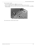
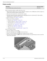
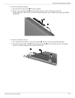
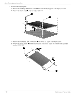
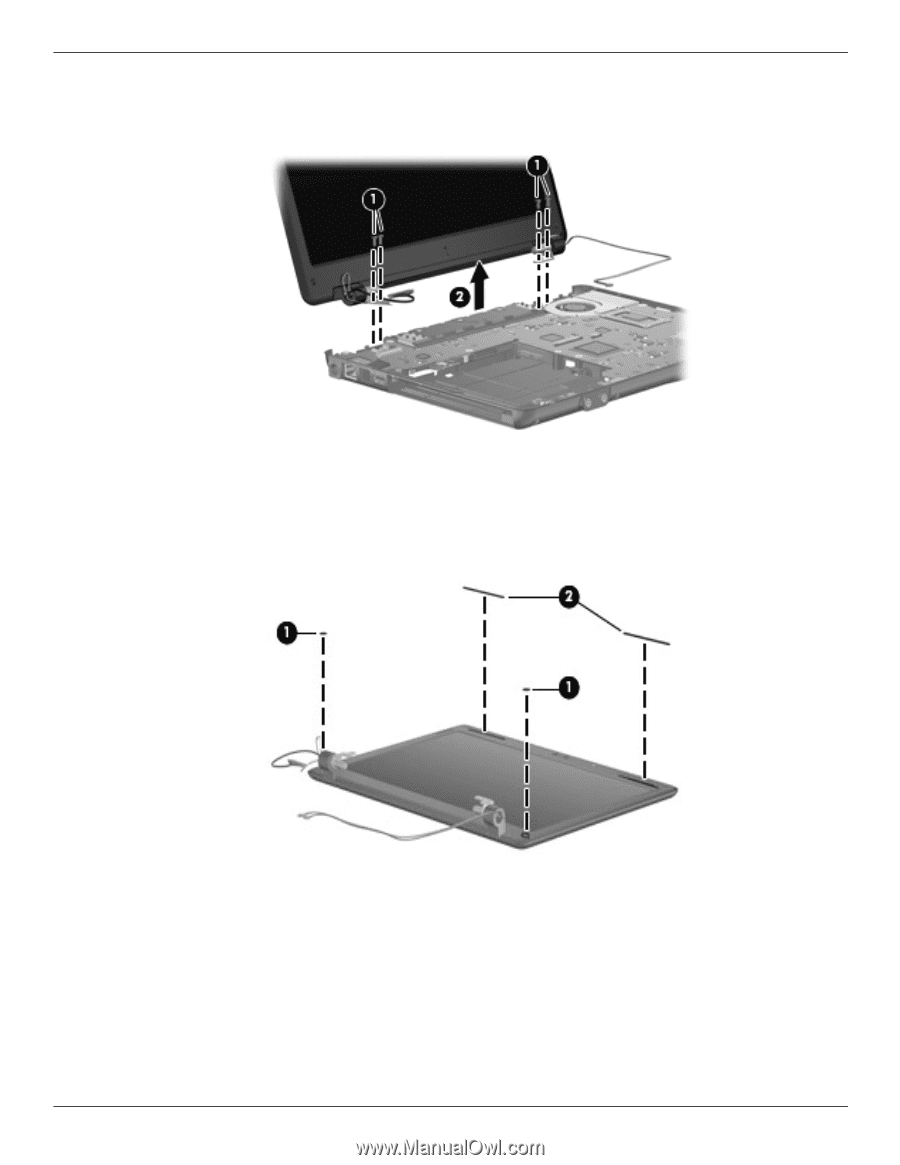
Removal and replacement procedures 5. Remove the four Torx T8M2.0×6.0 screws 1 that secure the display assembly to the computer. Be sure to hold the display before removing the last screw to prevent damage to the display. 6. Lift the display assembly 2 straight up and remove it. Perform the following steps in sequence to remove or replace the display bezel or the display assembly internal components. 1. To remove the display bezel: a. Remove the two rubber screw covers 1 at the bottom of the display assembly and peel back the two rubber bumper strips 2 at the top of the display assembly. Maintenance and Service Guide 4-25
-
 1
1 -
2
-
3
-
4
-
5
-
6
-
7
-
8
-
9
-
10
-
11
-
12
-
13
-
14
-
15
-
16
-
17
-
18
-
19
-
20
-
21
-
22
-
23
-
24
-
25
-
26
-
27
-
28
-
29
-
30
-
31
-
32
-
33
-
34
-
35
-
36
-
37
-
38
-
39
-
40
-
41
-
42
-
43
-
44
-
45
-
46
-
47
-
48
-
49
-
50
-
51
-
 52
52 -
 53
53 -
 54
54 -
 55
55 -
 56
56 -
 57
57 -
 58
58 -
 59
59 -
 60
60 -
 61
61 -
 62
62 -
63
-
64
-
65
-
66
-
67
-
68
-
69
-
70
-
71
-
72
-
73
-
74
-
75
-
76
-
77
-
78
-
79
-
80
-
81
-
82
-
83
-
84
-
85
-
86
-
87
-
88
-
89
-
90
-
91
-
92
-
93
-
94
-
95
-
96
-
97
-
98
-
99
-
100
-
101
-
102
-
103
-
104
-
105
-
106
-
107
-
108
-
109
-
110
-
111
-
112
-
113
-
114
-
115
-
116
-
117
-
118
-
119
-
120
-
121
-
122
-
123
-
124
-
125
-
126
-
127
-
128
-
129
-
130
-
131
 |
 |
Removal and replacement procedures
Maintenance and Service Guide
4–25
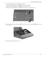
5. Remove the four Torx T8M2.0×6.0 screws
1
that secure the display assembly to the computer. Be sure to hold
the display before removing the last screw to prevent damage to the display.
6. Lift the display assembly
2
straight up and remove it.
Perform the following steps in sequence to remove or replace the display bezel or the display assembly internal
components.
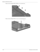
1. To remove the display bezel:
a.
Remove the two rubber screw covers
1
at the bottom of the display assembly and peel back the two rubber
bumper strips
2
at the top of the display assembly.