Corsair TX650 User Manual - Page 6
Step A: Building a brand new system, Step B: Replacing your existing power supply - manual
 |
View all Corsair TX650 manuals
Add to My Manuals
Save this manual to your list of manuals |
Page 6 highlights
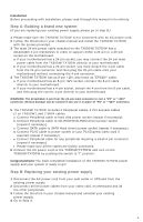
Installation Before proceeding with installation, please read through this manual in its entirety. Step A: Building a brand new system: (If you are replacing your existing power supply, please go to step B.) 1 Please make sure the TX650W/TX750W is not connected with an AC power cord. 2 Follow the directions in your chassis manual and install the TX650W/TX750W with the screws provided. 3 The main 24-pin power cable attached on the TX650W/TX750W has a detachable 4-pin mechanism in order to support either a 24-pin or a 20-pin socket on the motherboard. a If your motherboard has a 24-pin socket, you may connect the 24-pin main power cable from the TX650W/TX750W directly to your motherboard. b If your motherboard has a 20-pin socket, you must detach the 4-pin cable from the 24-pin connector, and then plug the 20-pin cable onto your motherboard without connecting the 4-pin connector. 4 The TX650W/TX750W has an 8-pin +12V; also know as "EPS12V" cable. a If your motherboard has an 8-pin +12V socket, connect the 8-pin cable directly to your motherboard. b If your motherboard has a 4-pin socket, detach the 4-pin from the 8-pin cable, and then plug the correct 4-pin directly to your motherboard. WARNING: The detachable 4-pin from the 24-pin main connector is not a "P4" or "+12V" connector. Serious damage can be caused if you use it in place of "P4" or "+12V" connector. 5 The TX650W/TX750W includes 2 Peripheral cables, 4 PCI-Express cables (2 on TX650W), and 2 SATA cables. a Connect Peripheral cable to hard disk power socket (repeat if necessary). b Connect Peripheral cable to CD-ROM/DVD-ROM drive's power socket (repeat if necessary). c Connect SATA cable to SATA Hard drive's power socket (repeat if necessary). d Connect PCI-E cable to power socket of your PCI-Express video card if required (repeat if necessary). e Connect Peripheral cable for any peripheral requiring a small 4-pin connector (repeat if necessary). f Please make sure all the cables are tightly connected. 6 Connect the AC power cord to the TX650W/TX750W and turn on the TX650W/TX750W by pushing the switch to "I" position. Congratulations! You have completed installation of the TX650W/TX750W power supply and your system is ready to go! Step B: Replacing your existing power supply 1 Disconnect the AC power cord from your wall outlet or UPS and from the existing power supply. 2 Disconnect all the power cables from your video card, motherboard and all the other peripherals. 3 Follow the direction in your chassis manual and uninstall your existing power supply. 4 Go to Step A. 6
-
 1
1 -
 2
2 -
 3
3 -
 4
4 -
 5
5 -
 6
6 -
 7
7 -
 8
8 -
 9
9 -
 10
10 -
 11
11 -
 12
12 -
13
-
14
-
15
-
16
-
17
-
18
-
19
-
20
-
21
-
22
-
23
-
24
-
25
-
26
-
27
-
28
-
29
-
30
-
31
-
32
-
33
-
34
-
35
-
36
-
37
-
38
-
39
-
40
 |
 |
