Craftsman 22124 Owners Manual
Craftsman 22124 - Professional 10 in. Table Saw Manual
 |
View all Craftsman 22124 manuals
Add to My Manuals
Save this manual to your list of manuals |
Craftsman 22124 manual content summary:
- Craftsman 22124 | Owners Manual - Page 1
SAW Model No. 152.221240 CAUTION: FOR YOUR OWN SAFETY; Read and follow all of the Safety and Operating Instructions before Operating this Table Saw. Customer Helpline 1-800-897-7709 Please have your Model No. and Serial No. available. Sears, Roebuck and Co., Hoffman Estates, IL 60179 U.S.A. Part - Craftsman 22124 | Owners Manual - Page 2
Grounding Instructions ...Specific Safety Instructions for Table Saw ...Accessories and Attachments ...Carton Contents ...Know Your Table Saw ...Assembly Instructions ...Operations and Adjustment to the Table Saw ...Maintenance ...Troubleshooting Guide ...Part List ...Espanol ...Service Information - Craftsman 22124 | Owners Manual - Page 3
anda mitercutatonetime. Crosscu-t Theoperatioonfmakinga cutacrossthe grainorwidthofa workpiece. Dado- Anon-througchutthatproduceassquarenotch. A dadoistypicallyfrom1/8-int.o 13/16 withouut singthefenceormitergaugeina cuttingoperation. Freehancdutsmustneverbeperformeodna Table Saw. Gum,Pitchor Resin- - Craftsman 22124 | Owners Manual - Page 4
are available at Sears Retail Stores. Hearing equipment should comply with ANSi $3.19 Standards To avoid serious injury and damage to the tool, read and follow all of the Safety and Operating Instructions before operating the Table Saw. 1. READ the entire Owner's Manual. LEARN how to use the tool - Craftsman 22124 | Owners Manual - Page 5
parts. A guard or other part that is damaged should be immediately repaired or replaced. 21. CHILDPROOF THE WORKSHOP AREA by removing switch keys, unplugging tools from the electrical receptacles, and using CORDS (AWG)" table for correct sizing of an extension cord. If in doubt, use the next heavier - Craftsman 22124 | Owners Manual - Page 6
replacement of the electric cord or plug is necessary. CHECK with a qualified electrician or service personnel if you do not completely understand the grounding instructions, or if you are not sure the tool is properly grounded. The motor supplied with your Table Saw can be used to temporarily - Craftsman 22124 | Owners Manual - Page 7
and wiring should be made by qualified personnel only. 8. DO NOT handle the plug or Table Saw with wet hands. 9. USE only as described in this manual. USE accessories only recommended by Sears. 10. DO NOT pull the Table Saw by the power cord. NEVER allow the power cord to come in contact with sharp - Craftsman 22124 | Owners Manual - Page 8
and fastened before table saw is to be connected to the power source. 33. ADDiTiONAL iNFORMATiON regarding the safe and proper operation of this product is available from the National Safety Council, 1121 Spring Lake Drive, Itasca, IL 60143-3201 in the Accident Prevention Manual for Industrial - Craftsman 22124 | Owners Manual - Page 9
Miter Gauge * Table Insert - Standard 29880 29882 * Table Insert - Dado 29885 * Table Insert - Molding Cutterhead * Saw Blade - Leitz; lO-in, x 40 tooth variable pitch blade * Fence Guide System 29887 29888 32371 Sears may recommend other accessories not listed in this manual. See your nearest - Craftsman 22124 | Owners Manual - Page 10
CONSTRUCTING A PUSHSTICK When ripping work less than 4 inches wide, a pushstick should be used to complete the feed and could easily be made from scrap material by following the pattern 2C should be copied and scaled so the grids are 1/2 inch square. This copy can be used to make your pushstick. 10 - Craftsman 22124 | Owners Manual - Page 11
" after all the parts have been obtained and installed correctly. TABLE SAW 1. Table saw assembly 2. Extension wing (2) 3. Handwheel (2) 4. Handwheel lock knob (2) 5. Splitter mounting rod 6. Splitter bracket assembly 7. Wrench hook 8. Leveling foot (4) 9. Fence hook (2) 10. Polly-V belt 11. Blade - Craftsman 22124 | Owners Manual - Page 12
FENCE 20. Rearrail 21. Frontrail 22. Guidetube Fig. 3-2 22 21 23 2O 23. Extensiontableassembly 24. T-Squar_e)fenceassembly 25. Lockinghandleknob 26. Cursor(2) 27. Template / 27 26 MITER GAUGE 40. Miter gauge 41. Cross cut fence 42. Depth stop 43. Clamp assembly 44. M5 x 20mm Hex socket - Craftsman 22124 | Owners Manual - Page 13
OUTFEED TABLE 50. Outfeed table assembly 51. Hinge assembly (2) 52. Clamp knob 53. Upper support assembly 54. Lower support 55. Support retainer Fig. 3=4 5O 51 52 55 53 54 Hardware packs are not identified or labeled. See hardware diagram to help in finding the correct part. See figure 3-5. , - Craftsman 22124 | Owners Manual - Page 14
Fig. 3=5 HEX HEAD SCREW N8xI.25 x 25_M HEX HEAD _REW MSx|.25 x 3O_a @8 HEX HEAD SCREW 5/|6-|8 × |-i/2" 0 @ HEX HEAD SCREW 0 N6 x 25_ @ HEX HEAD SCREW N6 x 35_ HEX NUT N8×1.25 @El HEX Nut 5/16°=18 @I @8 HEX NUT M6, NYLOCK @B HEX NUT M5 HEX HEAD SCREW 1/4-20 x i12" FLAT WASHER N8 HEX - Craftsman 22124 | Owners Manual - Page 15
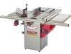
Blade guard 5. Align-a-cut insert 6. Rear out-feed table 7. Table surface 8. 12-in. cast iron wing 9. Biesemeyer commercial T-square fence 10. Accessory Biesemeyer extension table 11. Front rail with scale 12. Rip fence handle 13. Motor cover 14. Bevel scale 15. Full cabinet 16. Leveling foot 17 - Craftsman 22124 | Owners Manual - Page 16
this entire Owner's Manual. LEVELING FEET ASSEMBLY NOTE: If you will be permanently attaching your table saw to the floor, DO NOT assemble leveling feet and go on to the next step. 1. With two people, tip the front of the table saw (A) back and block the table saw up using two small blocks - Craftsman 22124 | Owners Manual - Page 17
saw table. Use four M8 x 30mm hex head screws, M8 lock washers and M8 flat washers. Do not completely tighten hardware at this time. See figure 7-1. Figure 7=2 D E 1, Make sure all packaging material has been removed from inside the cabinet. 2. Open the motor cover and place the motor Poly-V belt - Craftsman 22124 | Owners Manual - Page 18
the cabinet. Align the groove (C) in the back of the handwheel with the pin (D). See figure 8-1. Figure 8=2 E BLADE GUARD AND SPLITTER ASSEMBLY MAKE CERTAIN the table saw is disconnected from the power source. 1. Remove the table insert. Note: Remove the table insert retaining bolt used to secure - Craftsman 22124 | Owners Manual - Page 19
Place a square (N) onto the saw table and against the splitter assembly the saw table. Once the table saw. Place Replace table insert and tighten table insert retaining bolt removed in step 1. 10. If there is any problem with the front splitter attachment bracket being out-of-square to the saw table - Craftsman 22124 | Owners Manual - Page 20
ASSEMBLY FRONT AND REAR RAiL ASSEMBLY SAW TABLE FRONT MAKE CERTAIN the table saw is disconnected from the power source. Figure 11=1 E E D C 4. Using the template (G), check and adjust front rail parallel to the table surface on both sides of the saw table. See figure 11-3. 5. When you are - Craftsman 22124 | Owners Manual - Page 21
the front and rear rails. Make sure the edge of the extension table assembly is flush against the right side of the extension wing (B). Using a straight edge or level (C) make certain the extension table is level to the saw table. Using a pipe clamp (not supplied) (D) snug up the ends of rails to - Craftsman 22124 | Owners Manual - Page 22
table and reposition it on left side of saw blade. Align right fence side at a distance from the left side of left miter gauge groove and lock the fence. 1, Attach support retainer (A) to the lower rear of the cabinet the guide tube measuring scale so that the thin black line is on the same number - Craftsman 22124 | Owners Manual - Page 23
(K) in the outfeed table align with the table saw's miter gauge grooves. Place a straight edge on the saw table overhanging the outfeed table. Make sure the outfeed table is level or slightly below the saw table and securely tighten hardware attaching support retainer to cabinet. 4. Make a loop - Craftsman 22124 | Owners Manual - Page 24
MITER GAUGE ASSEMBLY Figure 13=2 H MAKE CERTAIN the table saw is disconnected from the power source. Figure 13-1 E B the cross cut fence so that no part of the fence is in the path of the saw blade. Allow the cross cut fence to rest on the saw table and securely tighten both hex socket head - Craftsman 22124 | Owners Manual - Page 25
the floor. To attach to the floor, see instructions below. Figure 13A-1 A C C A D 1. Remove the four leveling feet (A) from the table saw (B). See Figure 13A-1. 2. Remove six Phillip head screws (C) and remove dust spout (D) from the back of the cabinet. Figure 13A-2 5. Remove nine Phillip head - Craftsman 22124 | Owners Manual - Page 26
• A separate electrical circuit should be used for your table saw. The table saw comes pre-wired for 120-volt use. The circuit should not be less than #14 AWG wire and should be protected with a 15-amp time lag fuse. • Have a qualified electrician repair or replace damaged or worn cord immediately - Craftsman 22124 | Owners Manual - Page 27
positive stop, raise the saw blade to its highest position. 6. Using a combination square (D) check that the blade is 45-degrees to the saw table (45-degrees on tighten bevel handwheel lock knob, located on the left side of the cabinet. This will keep the blade from further tilting. Turn the set - Craftsman 22124 | Owners Manual - Page 28
on the bevel scale (B) located on the front of the cabinet. See figure 17-1. 3. To adjust arrow, loosen the Philips using a dial indicator (not included) or a combination square (not included). It is recommended to check the alignment before initial operation as follows: MAKE CERTAIN the table saw - Craftsman 22124 | Owners Manual - Page 29
C C MAKE CERTAIN the table saw is disconnected from the power source when making adjustments. Figure 18=1 A G B 1. To move the rip fence (A) along the guide tube (B), simply lift up blade to 45 degrees, and rotate the saw blade by hand. Make sure the blade does not contact the table insert. 29 - Craftsman 22124 | Owners Manual - Page 30
TABLE INSERT ADJUSTMENT MAKE CERTAIN the table saw is disconnected from the power source when making adjustments. Figure 194 C 4, Slightly tighten or loosen one of the two adjusting screws ([), using a 3/16" hex wrench, (not supplied). See figure 18-2. 5, Replace the rip fence on the guide tube - Craftsman 22124 | Owners Manual - Page 31
the front of the saw table and assemble the blade flange and arbor nut. Using both blade wrenches as previously mentioned, tighten arbor nut in the opposite direction from which it was loosened. 6. Replace table insert and tighten the table insert retaining bolt. 7. Replace blade guard and splitter - Craftsman 22124 | Owners Manual - Page 32
industrybest tolerances. MITER GAUGE OPERATION AND ADJUSTMENT MAKE CERTAIN the table saw is disconnected from the power source when making adjustments. positive stops at O-degree and plus or minus 45-degrees or it can be manually set at any angle between plus or minus 60-degrees. 2. To rotate miter - Craftsman 22124 | Owners Manual - Page 33
G D CLAMP AND FENCE STOP OPERATION MAKE CERTAIN the table saw is disconnected from the power source when making adjustments. to the saw blade. Insert the guide bar into the miter gauge groove and slide the miter gauge up to the saw blade. 9. To check, place a square against the saw blade and - Craftsman 22124 | Owners Manual - Page 34
of the miter gauge (A) to position and guide the workpiece (B). See figure 24-1. Figure 24=2 The use of non-Craftsman attachments and accesE sories may result in risk of injury or damage to the table saw. Fig 24=1 D A TO CROSSCUT: 1. Place the workpiece against the miter gauge and advance both - Craftsman 22124 | Owners Manual - Page 35
saw table. The blade guard (B) and splitter assembly (C) must be used. The splitter has anti-kickback fingers (D) to prevent the workpiece from kicking back, and the splitter assembly to prevent the wood kerf from closing and binding on the blade. See figure 25-1. An accessory Craftsman Fence Guide - Craftsman 22124 | Owners Manual - Page 36
the outside arbor flange, for it will be needed when reattaching a blade to the saw arbor. Also, an accessory dado blade table insert (H) (not included) must be used in place of the standard table insert. See figure 26-4. Figure 264 H o (NOT INCLUDED) The blade guard and splitter assembly cannot - Craftsman 22124 | Owners Manual - Page 37
the outside arbor flange, for it will be needed when reattaching a blade to the saw arbor. Also, an accessory molding cutterhead table insert (F) (not included) must be used in place of the standard table insert. See figure 27-2. Figure 27=3 G A C The molding head consists of a cutterhead (A) in - Craftsman 22124 | Owners Manual - Page 38
to avoid scratching or marring the cast iron surface. After all stains and/or rust have been removed, clean all oil and dirt from the table saw using a soft cloth or rag. Lastly, you need to apply a good automotive paste wax to all unpainted cast iron surfaces. This will help to protect the - Craftsman 22124 | Owners Manual - Page 39
in safe order. CAUTION: DO NOT USE FLAMMABLE MATERIALS to clean tame saw. Only trained personnel should perform repairs to the table saw. Contact your nearest Sears Service Center for authorized service. Unauthorized repairs or replacement with non-factory parts could cause serious injury to the - Craftsman 22124 | Owners Manual - Page 40
table saw, turn the power switch to the "OFF" position and unplug the power cord from the electrical receptacle before making any adjustments. PROBLEM Blade is warped. 2. Drive belt is damaged. 3. Work surface is uneven. 4. Saw is not mounted securely. 40 1. Sharpen or replace blade. 2. Adjust - Craftsman 22124 | Owners Manual - Page 41
MODEL NO.152.221240 When servicing, use only CRAFTSMAN replacement parts. Use of any other parts may create a HAZARD or cause product damage. Any attempt to repair or replace electrical parts on this table saw may create a HAZARD unless a qualified service OWNER'S MANUAL - #22124 10" TaNe Saw - Craftsman 22124 | Owners Manual - Page 42
x 3/8" CABINET ASSEMBLY SPEC TAG (C SAW) BEVEL x 3/8" MODEL NO.152.221240 Qty. Key No. PART No. INSERT 1 420 OR91654 1/4-20 NYLON INSERT 1 421 OR91667 3/8-16 x 5/16" SOCKET HEAD SET SCREW 2 422 OR91610 PAD, WEAR 2 423 OR91601 FENCE SIDE REPLACEMENT KIT, 42" WHITE (SEE SERVICE - Craftsman 22124 | Owners Manual - Page 43
39A ( co o Z w rr_ 09 > 3B i 0 rn rZ P 136 4_ 0 - Craftsman 22124 | Owners Manual - Page 44
? Z F" m I 0 m z .o P m_ - Craftsman 22124 | Owners Manual - Page 45
PI_P|I|II|, o Z w pro O9 > 3°2l ,$303(3) I:l__°'- 301B 304A O ITI r" Z .o _o 4_ o - Craftsman 22124 | Owners Manual - Page 46
10-iN. TABLE SAW MODEL NO.152.221240 366(8) 365(1 564(2) 367(8) 35O Z,36,3(8) 362 361 360 359 358 355(2) 46 - Craftsman 22124 | Owners Manual - Page 47
1O-INT. ABLESAW MODEL NO.152.221240 402 40 t 406 413 .-"_---42t (2) 415 \ 416 434 435 428 445 446 4.32(3) 47 - Craftsman 22124 | Owners Manual - Page 48
fuerza (maximo desarrollado) 3450 R.P.IVI. (R.P.M. sin carga) No. de IVIodelo 152.221240 de 1 pu f PRECAUCION: PARA SU SEGURIDAD PERSONAL: Lea y obedezca todas las listo su No de Modelo y No. de Serie. Sears, Roebuck and Co., Hoffman No. de Modelo OR91552 Revisado: REV. D Estates, 48 IL - Craftsman 22124 | Owners Manual - Page 49
tambien podr_ tener otros derechos que variar_n de un estado a otro. Sears Roebuck and Co., Dept 817 WA, Hoffman Estates, IL 60179 Sierra /16 pulg. 8 pulg. 12 pulg., hierro fundido 330 Ibs. 70 Ibs. Haga use de la protecci6n de circuitos correcta para evitar los cheques electricos a s[ mismo y el - Craftsman 22124 | Owners Manual - Page 50
de Mesa. Mesa/zona de trabajo - La superficie total de la parte superior de la sierra de mesa sobre la que descansa el material mientras o comprarse para ayudar a empujar el material a traves de la hoja. Se hace use de una vara de empuje para evitar que las manos del operario entren en contacto - Craftsman 22124 | Owners Manual - Page 51
de herramientas mecanicas. Las Gafas de Protecci6n est&n disponibles en las tiendas Sears de ventas al detal. El equipo auditivo debe cumplir con la Normativa de Mesa. 1. LEA a conciencia el Manual del Propietario. APRENDA a c6mo hacer use de esta herramienta para sus aplicaclones diseSadas. - Craftsman 22124 | Owners Manual - Page 52
dispersar polvo u otras part[culas aereas, incluyendo polvo de madera, polvo de sflice cristalino y polvo de asbesto. Dirija las part[culas en la direcci6n es aceptable. Aseg0rese de que las dimensiones de su extensi6n electrica sear las correctas y que se encuentre en buen estado electrico. Repare - Craftsman 22124 | Owners Manual - Page 53
ESTA HERRAMIENTA DEBE ESTAR CONECTADA A TIERRA DURANTE EL USO PARA PROTEGER AL OPERARIO CONTRA LOS CHOQUES ELE_CTRICOS. EN EL CASO DE UN MALFUNCIONAMIENTO O AVERIA, la conexi6n a tierra ofrece el trecho de menor resistencia para la corriente electrica y reduce el riesgo de los choques electricos. - Craftsman 22124 | Owners Manual - Page 54
No la exponga a la Iluvia, ni haga use de ella en lugares ht]medos. INSTRUCCIONES DE de polvo diseBadas especialmente para filtrar las part[culas microsc6picas. 6. PARA REDUCIR EL RIESGO s61o come se describe en este manual. Utilice accesorios recomendaos por Sears solamente. 10. JAMAS tire de - Craftsman 22124 | Owners Manual - Page 55
con el material contra la hoja. 20. JAMAS realice operaciones "a mane libre'. Haga use de la gufa de corte o de la gufa de ingletes para orientar y guiar el est& disponible de parte del National Safety Council, 1121 Spring Lake Drive, Itasca, IL 60143-3201 en el Manual de Prevenci6n de Accidentes - Craftsman 22124 | Owners Manual - Page 56
Gu/as 29879 29880 29882 29885 29887 29888 32371 Sears podra recomendar otros accesorios no listados en este manual. Consulte su Departamento de Ferreteffa de Sears mas cercano o el Catalogo de Herramientas Electricas y de Mano de Sears para otros accesorios. No utilice ning0n accesorio a menos que - Craftsman 22124 | Owners Manual - Page 57
CONSTRUYENDO UNA VARA DE EMPUJE Durante el corte a Io largo de materiales con menos de 4 pulgadas de ancho, se debe hacer uso de una vara de empuje para completar la alimentaci6n. Puede construirse facilmente utilizando material descartado y siguiendo el patr6n ilustrado en la Figura 2C. Fig. 2C La - Craftsman 22124 | Owners Manual - Page 58
DESEMPACANDO Y REVISANDO EL CONTENIDO Figura 3-1 La sierra de mesa es una maquina pesada. Se requieren dos personas para desempaquetarla y levantar la sierra de mesa. Esta sierra de mesa requerira cierta cantidad de ensamblado. Esta sierra de mesa se env[a en dos cajas individuales, una para la - Craftsman 22124 | Owners Manual - Page 59
GUiA Figura. 3-2 20. Riel posterior 21. Riel delantero 22. Tubo de gufa 22 21 23 20 23. Ensamblado de extensi6n de mesa 24. Ensamblado de la gufa de la escuadra en T 25. Perilla de la agarradera de cierre 26. Cursor (2) 27. Plantilla 26 ESCUADRA DE INGLETES 40. Escuadra de ingletes 41. - Craftsman 22124 | Owners Manual - Page 60
MESA DE AVANCE DE SALIDA 50. Ensamblado de la mesa de avance de salida 51. Ensamblado de bisagras (2) 52. Perilla de abrazadera 53. Ensamblado de soporte superior 54. Soporte inferior 55. Reten del soporte Figura. 3-4 5O 51 52 55 53 54 Los estuches de ferreter[a no estan identificados ni - Craftsman 22124 | Owners Manual - Page 61
Fig. 3-5 © TORNILLO DE CABEZA HEX M8 x 1.25 x 25 mm TORNILLO DE CABEZA HE× M8 x 1.25 x 30 mm T©RNILL© DE CABEZA HEX 5/16-18 x 1-1/2 pulg. O © TORNILLO DE CABEZA HEX M6 x 25 mm O © TORNILLO DE CABEZA HEX M6 x 35 mm © TORNILLQ DE CABEZA HEX 1/4-20 x 1/2 pulg. © T©RNILLO DE CABEZA HEX 1/4-20 - Craftsman 22124 | Owners Manual - Page 62
24 2 43 1 6 23 7 8 9 10 11 22 17 14 15 1. Ensamblado del hendidor 2. Dedos anticontragolpe 3. Hoja 4. Protector de hoja 5. Pieza inserta de alineamiento de corte 6. Mesa posterior de avance de salida 7. Superficie de la mesa 8. Aia de hierro fundido de 12 pulg. 9. Gufa comercial - Craftsman 22124 | Owners Manual - Page 63
maquina se encuentre completamente montada y haya lefdo y entendido este Manual del Operario cabalmente. MONTAJE DE LOS PIES NWELADORES ASEGORESE de que desde por debajo de la sierra de mesa y col6quelos debajo de la parte posterior de la sierra. Repita estos pasos para conectar los dos pies - Craftsman 22124 | Owners Manual - Page 64
MONTAJE DE LA CORREA POLY-V ASEGORESE de que la sierra de mesa este desconectada de la fuente de energfa. Figura 64 B 1. PRECAUCION: Las alas de extensi6n son pesadas. Se requieren dos personas para ensamblar ambas alas de extensi6n a la sierra de mesa. 2, Monte una de las alas de extensi6n (A) - Craftsman 22124 | Owners Manual - Page 65
de la fuente de energfa. Figura 94 2, Coloque el extremo roscado de la vara de montaje del hendidor (A) a traves del agujero (B) en la parte posterior del gabinete. Coloque una tuerca hexagonal M12 (no ilustrada) sobre el extreme roscado de la vara de montaje del hendidor dentro del gabinete - Craftsman 22124 | Owners Manual - Page 66
que quede en Ifnea recta con la hoja, y apretando el unico tornillo de cabeza hueca hexagonal (U) en la parte superior del ensamblado de soporte del hendidor. Ver la figura 10-6. 6, Coloque la hoja de sierra de 10 pulg SOPORTE DEL HENDIDOR" en la secci6n de Operaciones y Ajustes de este manual. 66 - Craftsman 22124 | Owners Manual - Page 67
de mentaje del todo en este memento. Ver figura 11-1. 2, Aseg0rese de que el borde superior (C) del riel delantero este por debajo de la parte superior de la mesa de la sierra (D) y que el riel delantero no este bloqueando los extremes de las ranuras de la escuadra de ingletes (E). 3, Termine - Craftsman 22124 | Owners Manual - Page 68
IMPORTANTE: No utilice la plantilla suministrada para fijar el riel trasero. 8, Aseg0rese de que el borde superior del riel delantero este por debajo de la parte superior de la mesa de la sierra y que el riel delantero no este bloqueando los extremos de las ranuras de la escuadra de ingletes. 9, - Craftsman 22124 | Owners Manual - Page 69
11-9. 2, Alinee el lado izquierdo de la gufa (C) a cierta distancia del lado derecho (D) de la ranura de la escuadra de ingletes derecha, enclavando la gufa. 3, Use una cinta de medir para medir la distancia entre el lado derecho de la hoja de la sierra hasta el lade izquierdo de la gufa - Craftsman 22124 | Owners Manual - Page 70
por debajo de la mesa de avance de salida. No apriete la ferreteria completamente. 6, Monte las bisagras en la mesa de avance de salida a la parte superior del riel trasero a traves de los agujeros existentes, usando para ello cuatro tornillos de cabeza hexagonal M5 x 16 mm, arandelas de cierre M5 - Craftsman 22124 | Owners Manual - Page 71
tornillo de cabeza hueca hexagonal hasta que el tornillo quede parejo con la parte trasera de la tuerca cuadrada. Repita este paso para una arandela plana, 13-2. 6, Posicione la gufa de corte transversal de tal manera que ninguna parte de la gufa se encuentre en el trayecto de la hoja de la sierra - Craftsman 22124 | Owners Manual - Page 72
de cabeza Phillips (C) y quite el surtidor de polvo (D) de la parte posterior del gabinete. FIgura 13A-2 5, Quite los nueve tornillos de cabeza los dos tornillos de cabeza Phillips (G) de la placa de notaciones CRAFTSMAN (H). AVlSO: Estos dos tornillos de cabeza Phillips tienen tuercas hexagonales - Craftsman 22124 | Owners Manual - Page 73
PRECAUCI6N * Debe hacerse use de un circuito electrico individual para su sierra de mesa. quitadas y colocadas en d6nde no pueda alcanzarlas ningt]n niflo. Ver la figura 14-1. 3. Para hacer use de la sierra de mesa, abra el candado y retfrelo del bot6n de "ENCENDIDO". PROTECClC)N CONTRA SOBRECARGAS - Craftsman 22124 | Owners Manual - Page 74
Parabajarlahojadelasierraa, flojelaperilladecierredel volantdeemane(ensentidaontihorariyog) ireelvolantdee maneensentidaontihorarCiou. andloahojadelasierrase encuentraelaalturadeseada,prietelaperilladecierredel volantdeemane(ensentidhoorarioh)astaqueeste afianzadsaeguramente. INCLINANDO LA HOJA El - Craftsman 22124 | Owners Manual - Page 75
atras para que pueda tomar las medidas desde el mismo punto en la hoja de la sierra. Ver figura 17A-2. 7, Tome una lectura en la parte posterior de la hoja (E) con la escuadra de combinaciones. Si hay una diferencia de mas de cuatro espacios de papel estandar de impresora entre la - Craftsman 22124 | Owners Manual - Page 76
Figura 17B=1 / ® \ [ BIESEMEYER ENSAIVIBLADO DEL SISTEMA COMERClAL DE GUiA DE CORTE A LO LARGO CON ESCUADRA "T" DE BIESEMEYER OPERACIONES Y AJUSTES A B Para alinear el paralelo de la hoja con la ranura de ingletes, afloje primero las dos tuercas de cabeza hexagonal (A) debajo del lado - Craftsman 22124 | Owners Manual - Page 77
mesa, afloje y remueva el perno de reten de la pieza de inserci6n de mesa (C). Ver la figura 19-1. 2, Coloque una regla sobre el frente y la parte trasera de la pieza de inserci6n de mesa. Revise que la pieza de inserci6n este perfectamente nivelada con la mesa de la sierra. 3, Para nivelar - Craftsman 22124 | Owners Manual - Page 78
y eleve la hoja de la sierra a su altura maxima. 4. Se suministran dos Ilaves con la sierra de mesa. Coloque una Ilave de boca (A) sobre la parte plana del eje de la sierra para evitar que gire. Coloque la Ilave de extreme cerrado (B) sobre la tuerca del eje (C). Gire la Ilave de - Craftsman 22124 | Owners Manual - Page 79
ALINEANDO EL SOPORTE DEL HENDIDOR ASEGORESE de que la sierra de mesa este desconectada de la fuente de energ[a. Figura 21A=1 A B 1. Para ajustar el soporte del hendidor delantero (A), afloje los dos tornillos de cabeza hueca hexagonal (B). Ver Fig. 21A-1. Figura 21A=2 3, Vuelva a apretar los dos - Craftsman 22124 | Owners Manual - Page 80
el embolo, apretando la tuerca de cierre despues. Ver la figura 22-2. 8, Vuelva a revisar el angulo del tope positivo con la hoja de la sierra. Inserte la barra de gufa dentro de la ranura de la escuadra de ingletes y deslice la escuadra de ingletes hasta la hoja de la sierra. 9. Para - Craftsman 22124 | Owners Manual - Page 81
use de la escuadra de ingletes (A) para posicionar y guiar el material (B). Ver la figura 24-1. El uso de aditamentos y accesorios que no sean de Craftsman 24-3. PRECAUCION Cuando vaya a hacer use del bloque come calibre de corte, es muy importante que la parte trasera del bloque este posicionado de - Craftsman 22124 | Owners Manual - Page 82
borde externo de la gufa. 5. La parte troceada del material permanece sobre la mesa y menos de 4 pulg. de ancho, debe hacerse use siempre de una varilla de empuje (E) o gu Craftsman de accesorio como ayuda cuando vaya a efectuar cortes angostos. Vea la secci6n "ACCESORIOS Y ADITAMENTOS" en este manual - Craftsman 22124 | Owners Manual - Page 83
DE FRESAS ROTATIVAS DE RANURAR El protector de hoja y ensamblado del hendidor no puede utilizarse durante el fresado o moldurado y debe bascularse hacia la parte trasera de la sierra. El protector de hojas debe reensamblarse una vez que haya completado el fresado o moldurado. Figura 26=1 B Los - Craftsman 22124 | Owners Manual - Page 84
Figura 26-5 El protector de hoja y el ensamblado del hendidor no pueden utilizarse durante el fresado o el moldurado y deben bascularse hacia la parte trasera de la sierra• El protector de hoja debe reensamblarse cuando haya terminado. Figura 27-2 D La Figura 26-5 muestra una operaci6n tfpica de - Craftsman 22124 | Owners Manual - Page 85
producira contragolpes. PRECAUClON Durante el moldurado a contrahilo debe hacerse use de la escuadra de ingletes. La velocidad de alimentaci6n debe hierro moldeado sin pintar. Aseg0rese de pulir en sentido "del frente a parte posterior" solamente. El pulido de lado a lado aparecera en el hierro - Craftsman 22124 | Owners Manual - Page 86
parte del operario. LIMPIEZA Con la sierra de mesa desenchufada, sople aire a baja presi6n sobre el motor para quitar el polvo o la suciedad. No debe hacerse use sierra de mesa. Comunfquese con su Centre de Servicio Sears mas cercano para obtener servicio autorizado. Las reparaciones desautorizadas - Craftsman 22124 | Owners Manual - Page 87
Para evitar herirse a si mismo o daRar la sierra de mesa, conmute el interrupter de energfa a "APAGADO" y desenchufe el cord6n de potencia del tomacorrientes antes de realizar cualquier ajuste. PROBLEMA Motor no arranca: CAUSAS POSIBLES 1. Interruptor no fue oprimido a suficiente profundidad o - Craftsman 22124 | Owners Manual - Page 88
it! For the replacement parts, accessories and owner's manuals that you need to do-it-yourself. For Sears professional installation of home service en frangais: 1-800-LE-FOYER Mc (1-800-533-6937) www.sears.ca © Sears, Roebuck and Co. @ Registered Trademark / TMTrademark / sMService Mark of Sears
-
 1
1 -
 2
2 -
 3
3 -
 4
4 -
 5
5 -
 6
6 -
 7
7 -
8
-
9
-
10
-
11
-
12
-
13
-
14
-
15
-
16
-
17
-
18
-
19
-
20
-
21
-
22
-
23
-
24
-
25
-
26
-
27
-
28
-
29
-
30
-
31
-
32
-
33
-
34
-
35
-
36
-
37
-
38
-
39
-
40
-
41
-
42
-
43
-
44
-
45
-
46
-
47
-
48
-
49
-
50
-
51
-
52
-
53
-
54
-
55
-
56
-
57
-
58
-
59
-
60
-
61
-
62
-
63
-
64
-
65
-
66
-
67
-
68
-
69
-
70
-
71
-
72
-
73
-
74
-
75
-
76
-
77
-
78
-
79
-
80
-
81
-
82
-
83
-
84
-
85
-
86
-
87
-
88
 |
 |

Owner's
uai
CRRFrSMRH
1.75
Horsepower
(continuous
duty)
2.4
Horsepower
(maximum
developed)
3450
R.P.M.
(no
load
R.P.M.)
10-in.
TABLE
SAW
Model
No.
152.221240
CAUTION:
FOR
YOUR
OWN
SAFETY;
Read
and follow
all of the Safety
and
Operating
Instructions
before
Operating
this
Table
Saw.
Customer
Helpline
1-800-897-7709
Please
have your
Model
No.
and Serial
No. available.
Sears,
Roebuck
and
Co.,
Hoffman
Estates,
IL 60179
U.S.A.
Part No. OR91552
Revision:
D
Espa5ol
pg. 48