Craftsman 22901 Instruction Manual
Craftsman 22901 - Professional 17 in. Drill Press Manual
 |
View all Craftsman 22901 manuals
Add to My Manuals
Save this manual to your list of manuals |
Craftsman 22901 manual content summary:
- Craftsman 22901 | Instruction Manual - Page 1
215 - 2720 R.P.M. Drill Speed Range 1 iLL P SS Model No. 152.229010 C S FOR YOUR OWN SAFETY; Read and foUlow all of the Safety and Operating Instructions before Operating this DdH Press. Customer Helpline 1-800-897-7709 PRease have your Model No. and SedaR No. availabUe. Sears, Roebuck and - Craftsman 22901 | Instruction Manual - Page 2
Maintenance ... 26 Troubleshooting Guide ... 27 Part List ... 28 EspaSol ... 3! Service Information ... Back Page ONE-YEAR FULL WARRANTY ON CRAFTSMAN TOOL if this Craftsman tool fails due other rights, which vary from state to state, Sears, Roebuck and Co,, Dept 817WA, Hoffman Estates, IL 60179 - Craftsman 22901 | Instruction Manual - Page 3
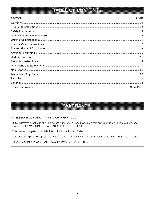
12 =3/4" 28-1/2" 198 pounds Yes Yes To avoid electrical shock to yourself and damage to the drill press, use proper circuit protection, Do not expose to rain, or use in a damp environment, The drill press is factory wired for 120V, 60 Hz, operation, Connect to a 120V, 15 amp branch circuit and - Craftsman 22901 | Instruction Manual - Page 4
and follow all of the Safety and Operating instructions before operating the drill press, 1, READ the entire instruction Manual, LEARN how to use the tool for Z87,1) when operating power tools, Safety Goggles are available at Sears Retail Stores, 3, ALWAYS WEAR HEARING PROTECTION, Plain cotton is - Craftsman 22901 | Instruction Manual - Page 5
, Use of incorrect or improper accessories could cause serious injury to the operator and cause damage to the tool, if in doubt, check the instruction manual that comes with that particular accessory, 26, USE A PROPER EXTENSION CORD IN GOOD CONDITION, When using an extension cord, be sure to use one - Craftsman 22901 | Instruction Manual - Page 6
cord or plug is necessary. CHECK with a qualified electrician or service personnel if you do not completely understand the grounding instructions, or if you are not sure the tool is properly grounded. The motor supplied with your Drill Press is a dual voltage 120/240 volts, 60 hertz alternating - Craftsman 22901 | Instruction Manual - Page 7
in a vise. 7. DO NOT operate this drill press until it is assembled and installed according to the instruction manual. 8. DO NOT leave the drill press plugged into the ebctrical outlet. Unplug the drill press from the outlet when not in use and before servicing, changing bits and cleaning. 9. DO NOT - Craftsman 22901 | Instruction Manual - Page 8
not listed in this manual, See your nearest Sears Hardware Department or Craftsman Power and Hand Tool Catalog for other accessories, Do not use any accessory unless you have completely read the instruction Manual for that accessory, Use only accessories recommended for this drill press, Using other - Craftsman 22901 | Instruction Manual - Page 9
Figure 2-1 i II 12 1, BeHtcover 2, ON/OFF switch 3, AdjustabHe feed handHes 4, QulH Hock 5, Laser (not shown) 6, KeyHess chuck 7, TaMe 8, CoHumn 9, Base 10, TaMe Extension 11, Tray 12, Depth scaHe 13, Motor 14, FHexibHeHamp - Craftsman 22901 | Instruction Manual - Page 10
; verify that all items are accounted for before discarding the shipping box, if there are any missing parts, call Customer Helpline 1-800-897-7709, The drill press is a heavy machine, two people may be required to unpack and lift machine, if any parts are missing, do not attempt to plug in the - Craftsman 22901 | Instruction Manual - Page 11
Figure 3-2 E G F H JKL BB E, TaMe extension F, Knob G, TaMe extension support H, Keyiess chuck i, Chuck arbor J, 2,5mm Hex wrench K, 3mm Hex wrench L, 5mm Hex wrench Z M, TaMe rabe/Mower handle N, Spindie adapter remover O, Knob (2) P, Tray, back Q, Tray R, CHamp - Craftsman 22901 | Instruction Manual - Page 12
machine is completely assembled and you read and understand the entire Instruction Manual. COLUMN, BASE and TABLE ASSEMBLY Figure 4-1 i [ upside down and place the table extension support (K) into the bottom of the table. NOTE: The table extension support can be positioned either to the right - Craftsman 22901 | Instruction Manual - Page 13
tame rotation lock handle is the smaller of the two lock handles, See Figure 4-6 7, Insert the tame (J) into the mounting hole (P) tame support, Rotate the tame to desired position and tighten tame rotation locking handle, See Figure 4-6, 9, Assemble the threaded knob (R) into the weld nut (S) on - Craftsman 22901 | Instruction Manual - Page 14
Figure 4-9 T X \ DRILL PRESS HEAD AND MOTOR ASSEMBLY The drHUpress is a heavy machine; two peopb may (A) until it rests on the ring (Y) and tighten both screws, See Figure 4-10 2, Align the drill press head with the table and base and tighten the two head locking screws (C), See Figure 5-2, 14 - Craftsman 22901 | Instruction Manual - Page 15
and turn the chuck barrel (J) counter-clockwise, Make sure the jaws are completely recessed inside the chuck, See figure 5-6, 6, Seat the chuck onto the drill press spindle as far as it wiii go, Carefully drive the chuck onto the spindle by placing a wooden block (K) under the chuck (L) and tap the - Craftsman 22901 | Instruction Manual - Page 16
9-volt battery (D) (not included) to battery terminal (E), 4, Place battery into battery compartment (F) and replace battery cover, A To help reduce the tendency of the drill press to tip over, slide, or walk, it can be fastened to the floor surface, The machine base has four hobs (A), one at each - Craftsman 22901 | Instruction Manual - Page 17
, unlock and remove the padlock from the "ON" button, 1, The ON/OFF switch (A) is located on the front of the drill press head, See Figure 8-1, 2. To turn the Drill Press on, press the green ON button (B) in one-half inch, Note: There is a safety feature on the switch to insure that the switch must - Craftsman 22901 | Instruction Manual - Page 18
lower the table (A) on the column (B), loosen the table lock handle (C), See Figure 10-1 and 10-2, Figure 10-2 A The flexible lamp (A) operates independently of the drill press and has its own power cord, To turn the lamp ON and OFF, rotate the switch (B) in the clockwise direction only, See Figure - Craftsman 22901 | Instruction Manual - Page 19
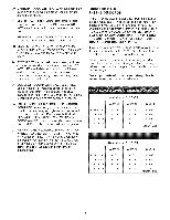
the correct spindle speed for your operation, This diagram can also be found on the inside of the belt cover of the drill press, Figure 11-1 Recommended Dri|| Press Speeds 6P|H6LE PULLEY s ,o !so 00IdB0,d I,°00,dy,I0B 0I°.,.mIst001 600 TwisDt rillBits _45 1/1B"=3/1B" 2720 2720 2720 2728 - Craftsman 22901 | Instruction Manual - Page 20
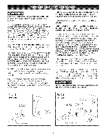
Hightfinger pressure, 6, Tighten both tension lock knobs, A C D 1, Insert the drill bit into the chuck and tighten, 2, Place the workpiece on the drill press table, Raise the drill press table until the workpiece is 1/8-in, from the drill bit, NOTE: Make sure the workpiece is secured to the table - Craftsman 22901 | Instruction Manual - Page 21
the handHe is reHeased, The return spring was properHy adjusted at the factory, However, to adjust, if necessary: ,, MAKE CERTAIN the drill press is disconnected from the power source, Figure 14-1 LASER ADJUSTMENTS ,, MAKE CERTAIN the drHHpress is disconnected from the power source, LASER LIGHT - Craftsman 22901 | Instruction Manual - Page 22
so that it is about 1" under the alignment pin, 12, Lay a 3/4" piece of wood (M) onto the drill press table under the line pin, See Figure 15-5, 13, Using the drift press feed handle, lower the alignment pin down and mark (N) the wood, Make sure the wood does not move, See Figure 15-5, 14 - Craftsman 22901 | Instruction Manual - Page 23
iNSTALLiNG AND REMOVING DRULL BITS MAKE CERTAIN the drill press is disconnected from the power source. Figure 18-1 SUPPORTING WOF{KPIECE USE onUyrecommended accessories. Figure 17-1 B o A HoUdthe collar (A) and turn the chuck barreU (B) counterocbckwbe to close the chuck jaws and clockwise to - Craftsman 22901 | Instruction Manual - Page 24
(A), loosen the two knobs (B) under the table (C), See Figures 19-1 and 19-2, 2, Position the tame extension support to its desired position and tighten the two knobs under the tame, 3, Ufthe height of the tame extension (D) needs to be adjusted, Uoosen the knob (E), 4, - Craftsman 22901 | Instruction Manual - Page 25
codes must be maintained, The motor supplied with the Drill Press is a dual voltage 120/240-volt, single phase motor, The motor is wired from the factory for 120-volt operation, To change to 240-volt operation, proceed with the following instructions, it is also necessary to replace the 120 volt - Craftsman 22901 | Instruction Manual - Page 26
surfaces, Make sure to buff out the wax before assembly, ONLY trained personnel should perform repairs to the drill press, Contact your nearest Sears Service Center for authorized service, Unauthorized repairs or replace° ment with non-factory parts could cause serious injury to the operator and - Craftsman 22901 | Instruction Manual - Page 27
thepowercordfromtheeUectrbareUceptaclebeforemakinganyadjustments, PROBLEM Motor #3 and #4 must be done by a qualified service technician; Consult Sears service. Motor stalls or circuit breakers open frequently 1. Circuit . See drill press head and motor assembly in "ASSEMBLY iNSTRUCTiONS". 27 - Craftsman 22901 | Instruction Manual - Page 28
Press MODELN0.152.229010 Retaining Split Bushing Handle Support MSxlOmm Hex Soc Set Holder Lasermodub Assy Hose Clamp Alignment Pin Door Laser Warning Label Padlock Assy (Not Shown) Owner's Manual (Not Shown) QTY. 1 1 1 2 1 1 1 1 1 1 1 1 2 1 2 1 1 1 1 1 1 2 1 1 1 4 8 4 4 4 1 1 1 1 1 1 1 1 1 1 1 1 - Craftsman 22901 | Instruction Manual - Page 29
17-in. Bench Drill Press {50 (2_. 151 (6)_ 158--_ # 155 (2)_ _g I_158 45 (2) /141 _/ 140 MODEL N0.152.229010 _5 (4) i 119 (2) 112 114 -% \49 (2) 52 / 103 (4}_ 102 (4)_ i01 {g)_ 29 - Craftsman 22901 | Instruction Manual - Page 30
30 - Craftsman 22901 | Instruction Manual - Page 31
Velocidades, Poiea Escalonada Gama de VeNocidades de Perforacidn 215-2720 R.P.M Modelo No. 152.229010 C S PARA SU SEGURJDAD PERSONAL, Reay obedezca todas Uas lnstrucciones de Seguddad y No. de Modelo y No. de Sede Sears, Roebuck and Co., Hoffman Estates, JL 60179 U.S.A. No. de Pieza OR93513 31 - Craftsman 22901 | Instruction Manual - Page 32
nformaci6n de $ervicio ... Contraportada GARANTiA COMPLETA DE UN ANO PARA LAS HERRAMIENTAS CRAFTSMAN Siesta herramienta Craftsman Ibgase a failar debido a defectos materiabs o de elaboraci6n dentro de un var[an de un estado al otto, Sears Roebuck and Co, Dept 817 WA, Hoffman Estates, iL 60179 32 - Craftsman 22901 | Instruction Manual - Page 33
Ta[adradora de Banco de 17 pu[g° con Laser°Trac TM _ecificaciones deI Motor: Tipo de motor Servicio continuo Maximo desarrollado Amperios Voltios Fase Hertzios R.RM. Inducci6n 3/4 HP 1-1/2 HP 10/5 120/240 Monofasico 60 1725 (sin carga) _ecificaciones deI Producto: Tipo de correa Tipo de poIea - Craftsman 22901 | Instruction Manual - Page 34
estar famifiarizado con et funcionamiento de esta herra- mienta. Lea este manual para entender esta taladradora. NO OPERE esta taladradora si no entiende de seguridad estg,n disponibles en las tiendas de Ventas al Detal de Sears. 3. UTILICE PROTECCION AUDmVA SlE_,_PRE. El algod6n por sf solo no - Craftsman 22901 | Instruction Manual - Page 35
21. NUNCADEJEUNAM_,QU_NEANFUNCJONAM_ENTODIRECTRJCES PARA LAS SiNATENDEARpaguelinterruptdeer energ[a Ia EXTENSUONES ELECTRICAS posici6dne"OFF("apagadoN).OsealejedeJambq,uina hastaquesehayadetenidpoercompbto. Mientras menor sea el n0mero de calibre, mayor sera el 22. - Craftsman 22901 | Instruction Manual - Page 36
ESTA HERRAM_ENTA DEBE ESTAR CONECTADA A TIERRA DURANTE EL USO PARA PROTEGER AL OPERAR_O CONTRA LOS CHOQUES ELECTR_COS. EN EL CASO DE UN MALFUNCJONAMJENTO O AVERJA, Jaconexi6n a tJerra ofrece eJ trecho de menor resistencia para Jacorriente electrica y reduce el riesgo de choque el6ctrico. Esta - Craftsman 22901 | Instruction Manual - Page 37
de seguridad estan disponibles en Jastiendas de Ventas al Detal de Sears. Deben seguirse ciertas precauciones bgsicas durante el uso de su taladradora de seguridad que aparecen a continuaci6n: 1. LEA y entienda el manual de instrucciones antes de operar esta herramienta mecb_nica. 12. ASEGURESE de - Craftsman 22901 | Instruction Manual - Page 38
AZAROSA A LA RADJACJON. taladradora y/o heridas graves. ACCESORJOS DISPONIBLES Visite su Departamento de Ferreteffa Sears o consuIte el CataJogo de Herramientas Manuales y Mecanicas de Craftsman para los siguientes accesorios: ART_CULO NO. DE EXISTENCJA *Cortadora de Circulos 25293 *Estuche - Craftsman 22901 | Instruction Manual - Page 39
Figura 2-1 i II 12 1. Cubierta de la correa 2. hterruptor de ENCENDIDO/APAGADO 3. Agarraderas de alimentaci6n ajustables 4. Cierre del Arbol hueco 5. LAser (no ilustrado) 6. Mandrino sin Ilave 7. Mesa 8. Columna 9. Base 10. Extensi6n de mesa 11. Bandeia 12. EscaJa de profundidad 13. Motor 14. - Craftsman 22901 | Instruction Manual - Page 40
DESEMPAQUE Y COTEJO DEL CONTENIDO Esta taladradora necesitara cierta cantidad de montaje. Quite todas Ias piezas de la caja de env[o y col6queias sobre una superficie de trabajo limpia. Quite todos Ios materiales y revestimientos protectivos de las piezas. Los revestimientos protectivos pueden - Craftsman 22901 | Instruction Manual - Page 41
Figura 3-2 E G F H JKL BB Z E. Extensi6n de mesa F. PerilIa G. Soporte de la extensl6n de mesa H. Mandrino sin Ilave I. Arbol del mandrino J. Llave hexagonal 2.5 mm K. Llave hexagonal 3 mm h Llave hexagonal 5 mm M. Agarradera de [zado / bajada de la mesa N. Desmontador del adaptador del huso - Craftsman 22901 | Instruction Manual - Page 42
seguridad, NO CONECTE la taladradora a la fuente de energ[a hasta que Ia maquina este completamente montada y usted haya le[do y entendido el manual de instrucciones cabalmente. MONTAJE DE LA COLUMNA, BASE Y MESA Figura 4-1 2= Conecte la agarradera de izado y bajada de la mesa (D) sobre el eje - Craftsman 22901 | Instruction Manual - Page 43
Figura 4-5 Figura 4-7 Q / C_ M 5. Coloque la placa de la abrazadera (L) sobre eI soporte de extensi6n de la mesa y conectela con dos perillas roscadas (M). Figura 4-6 J / 8. Coloque la extensi6n de mesa (Q) en el soporte de extensi6n de mesa. Ver Figura 4-7. Figura 4-8 R y .1. N 6, Monte el - Craftsman 22901 | Instruction Manual - Page 44
Figura 4-9 T X \ MONTAJE DEL CABEZAL Y MOTOR DE LA TALADRADORA La taladradora es una maquina pesada. Podran requedrse dos personas para ciertas operaciones de montaje, o ASEGORESE de que Ia taladradora este desenchufada de la fuente de suministro, Figura 5-1 A V 10, Monte sueltamente e! dorso de - Craftsman 22901 | Instruction Manual - Page 45
Figura 5-3 E Figura 5-5 IH G 3, Coloque la agarradera ajustable (D) sobre el eje de avarice del b,rbol hueco (E), Ver la Figura 5-3, Figura 5-4 F AVJSO: Aseg0rese de que la parte ahusada del huso (G) y eI agujero ahusado en eI mandfino (H) se encuentren Iimpios y fibres de grasa, Iaca o - Craftsman 22901 | Instruction Manual - Page 46
ENSAMBLADO DEL LASER o ASEGURESE de que la taiadradora este desconectada de la fuente de energ[a. o LUZ LASER - NO MIRE EL HAZ, LA APERTURA ni tampoco el refiejo de una superficie espejada. Figura 6-1 Figura 6-3 1. Coloque la abrazadera (A) a traves de las aberturas (B) en el alojamiento del Ib, - Craftsman 22901 | Instruction Manual - Page 47
o NO exponga la taladradora a Ja Jluvia ni tampoco Ja opere en Jugares hOmedos. ASEGURESE de que todas las piezas hayan sido correctamente montadas y esten en funcionamiento. OPERACION DEL CONMUTADOR Figura 8-2 HAGA SU TALLER A PRUEBA DE NINOS quitando las Jlaves de los interruptores, - Craftsman 22901 | Instruction Manual - Page 48
LAMPARA FLEXIBLE Para reducir el peIigro de incendios, utilice una bombilla de 40 vatios o menos, 120 voltios tipo reflector (no suministrado). NO UTILICE una bombilIa domestica estandar. La bombilla tipo reflector no debe extenderse mas alia de la pantalla de la lampara, Figura 9-1 B A - Craftsman 22901 | Instruction Manual - Page 49
Figura 10-3 Figura 10-4 G 20 o 100 0 10° 200 300 5. La mesa puede inclinarse a la derecha o izqu+erda afiojando el perno de cierre de Ia mesa (H)y Iuego quitando el pasador de alineaci6n de mesa (F). Ver Ia Figura 10+3+ 6. La mesa podra inclinarse ahora al _ngulo deseado. El perno de cierre de la - Craftsman 22901 | Instruction Manual - Page 50
CAMBIANDO VELOCIDADES Y AJUSTANDO LA TENSI6N DE LA CORREA PERFORANDO AGUJEROS A PROFUNDIDAD ASEGURESE de que la taladradora este desconectada de Ja fuente de energfa, Figura 12-1 ASEGURESE de que Jataladradora este desconectada de la fuente de energ[a, Figura 13-1 1, Abra Jacubierta de Ia correa - Craftsman 22901 | Instruction Manual - Page 51
AJUSTANDO EL RESORTE DE RETORNO El mandrino de la taladradora regresara Ientamente y de forma automatica a su posici6n superior aI soltar la agarradera. El resorte de retorno fue ajustado correctamente en Ia fabrica= Sin embargo, si resuIta necesario efectuar ajustes: ASEGURESE de que la taiadradora - Craftsman 22901 | Instruction Manual - Page 52
Figura 15-3 Figura 15-5 M J J 6. Afloje los dos tornillos d) sobre la cara (J) del laser del lade izquierdo. Ver la Figura 15-3. 7. En e! pasador de alineaci6n (A) existe una I[nea vertical de trazado (L). Esto se utiliza para establecer el paralelismo de los laseres. Ver Ia figura 15-4. 8. Usando - Craftsman 22901 | Instruction Manual - Page 53
INSTALACI6N DE BROCAS Y DESMONTAJE ASEGURESE de que la taladradora este desconectada de la fuente de energfa. Figura 18-1 APOYANDO EL MATERIAL SOLO utilice accesorios recomendados. Figura 17-1 B o A jB Sujete el collar[n (A) y gire el barriI del mandrino (B) en sentido antihorario para cerrar - Craftsman 22901 | Instruction Manual - Page 54
Figura 18-2 EXTENSION DE MESA Figura 19-1 C A D 2. Cuando la agarradera (A) este desengranada, gffela a Ia posici6n deseada y suelte Ia agarradera. La agarradera est9, cargada con resorte y se reengranar_i por s( sola al dejada descansar. Figura 18-3 Figura 19-2 D A A B C 3. La Figura 18-3 - Craftsman 22901 | Instruction Manual - Page 55
VELOCIDADES APROPIADAS DE PERFORACION Los factores que determinan Ia mqor velocidad a ser utiIizada en cualquier funci6n de taladrado son: eI tipo de material a ser elaborado, el tamaflo del agujero, tipo de broca u otra cortadora, y la calidad del corte deseado. Utilice la velocidad recomendada - Craftsman 22901 | Instruction Manual - Page 56
pulir la cera antes del montaie. SOLO personai competente debe realizar reparaciones a la taladradora. Comunfquese con su Centro de Servicio Sears mas cercano para recibir servicio autorizado. Las reparaciones o recambios desautorizados con piezas que no sean de fabrica podran causar heridas graves - Craftsman 22901 | Instruction Manual - Page 57
tomacorrientes. 5. Mande a recambiar el motor. AVlSO: 3 y 4 deben set realizados por un tecnico de servicio competente; consulte con el servicio de Sears. _,_otor se ahoga o los dieyuntores de eireuito se disparan con frecueneia 1. Sobrecarga de! circuito 2. Baja tensi6n de linea 3. Sobrecarga de - Craftsman 22901 | Instruction Manual - Page 58
12 Pumg, NO. DE MODELO 152,229010 Cuando vaya a rendir servicio, s6Jo utiIice piezas de recambio CRAFTSMAN. El uso de cuatquier otro tipo competente. El servicio de reparaci6n esta disponibJe en su Centro de Servicio Sears mas cercano. Encargue siempre per NOMERO DE HEZAy no per nOmero de - Craftsman 22901 | Instruction Manual - Page 59
Tatadradora de Banco de 12 Pumg, {50 (2_. 151 (6)_ 158--_ # 155 (2)_ _g I_158 _45 (2) _44 /141 _/ 140 NO, DE MODELO 152,229010 8 (2) 6 #_(4) _5 (4) i 119 (2) 112 {13 -% \49 (2) 52 / 103 (4}_ 102 (4)_ i01 {g)_ i00 (4)_ 59 - Craftsman 22901 | Instruction Manual - Page 60
replacement parts, accessories and owner s manuals that you need to do-it-yourself. For Sears professional installation of home appliances and items like only) www.sears.cor. To purchase a protection agreement (U.S.A.) or maintenance agreement(Canada) on a product serviced by Sears: 1-800-827-
-
 1
1 -
 2
2 -
 3
3 -
 4
4 -
 5
5 -
 6
6 -
 7
7 -
8
-
9
-
10
-
11
-
12
-
13
-
14
-
15
-
16
-
17
-
18
-
19
-
20
-
21
-
22
-
23
-
24
-
25
-
26
-
27
-
28
-
29
-
30
-
31
-
32
-
33
-
34
-
35
-
36
-
37
-
38
-
39
-
40
-
41
-
42
-
43
-
44
-
45
-
46
-
47
-
48
-
49
-
50
-
51
-
52
-
53
-
54
-
55
-
56
-
57
-
58
-
59
-
60
 |
 |

_truction
anu
®
rE lo..L"
3/4
Horsepower
(continuous
duty)
1-1/2 Horsepower
(maximum
developed)
16-Speed,
Step
Punmey
215 - 2720
R.P.M.
Drill
Speed
Range
1
iLL P
SS
Ji
Model
No.
152.229010
C
S
FOR
YOUR
OWN
SAFETY;
Read
and foUlow all of the Safety
and
Operating
Instructions
before
Operating
this
DdH Press.
Customer
Helpline
1-800-897-7709
PRease have your
Model
No.
and SedaR No. availabUe.
Sears,
Roebuck
and
Co.,
Hoffman
Estates,
JL 60179
U.S.A.
Part No. OR93513
EspaSoL pg, 31