Cub Cadet GT 1054 Operation Manual - Page 23
Leveling the Deck Side to Side, Parking Brake Adjustment, Adjusting the Seat, Steering Adjustment
 |
View all Cub Cadet GT 1054 manuals
Add to My Manuals
Save this manual to your list of manuals |
Page 23 highlights
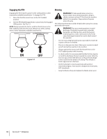
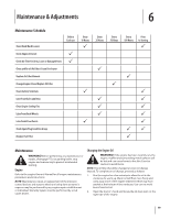
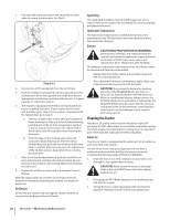
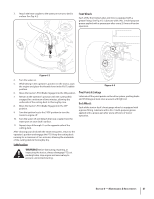
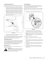
Leveling the Deck (Side to Side) If the cutting deck appears to be mowing unevenly, a side to side adjustment can be performed. Adjust if necessary as follows: 1. With the tractor parked on a firm, level surface, place the deck lift lever in the top notch (highest position) and rotate both blades so that they are perpendicular with the tractor. 2. Measure the distance from the outside of the left blade tip to the ground and the distance from the outside of the right blade tip to the ground. Both measurements taken should be equal. If they're not, proceed to the next step. 3. Loosen, but do NOT remove, the hex bolt on the left deck hanger bracket. See Fig. 6-5. Steering Adjustment If the tractor turns tighter in one direction than the other, or if the ball joints are being replaced due to damage or wear, the steering drag links may need to be adjusted. Adjust the drag links so that equal lengths of each are threaded into the ball joint on the left side and the ball joint on the right side: 1. Remove the hex nut below the ball joint. See Fig. 6-6. Adjustment Gear Ball Joint Hex Bolt Drag Link Hex Nut Figure 6-5 4. Using a wrench, raise or lower the left side of the deck by turning the adjustment gear. See Fig. 6-5. The deck is properly leveled when both blade tip measurements taken earlier are equal. Retighten the hex bolt on the left deck hanger bracket when proper adjustment is achieved. Parking Brake Adjustment If the tractor does not come to a complete stop when the brake pedal is completely depressed, or if the tractor's rear wheels can roll with the parking brake applied (and the hydrostatic relief valve open), the brake is in need of adjustment. See your Cub Cadet dealer to have the brake properly adjusted. Adjusting the Seat Refer to the Assembly & Set-Up section of this manual for seat adjustment instructions. Warning! Before operating the tractor, make sure the seat is engaged in the seat-stop. Engage the parking brake. Stand behind the machine and pull back on seat until it clicks into place. Figure 6-6 2. Thread the ball joint inward to shorten the drag link. Thread the ball joint outward to lengthen the drag link. 3. Replace the hex nut after proper adjustment is achieved. NOTE: Threading the ball joints too far onto the drag links will cause the front tires to "toe-in" too far. Proper toe-in is between 1⁄16" and 5⁄16". Front tire toe-in can be measured as follows: 1. Place the steering wheel in position for straight ahead travel. 2. In front of the axle, measure the distance horizontally from the inside of the left rim to the inside of the right rim. Note the distance. 3. Behind the axle, measure the distance horizontally from the inside of the left rim to the inside of the right rim. Note the distance. 4. The measurement taken in front of the axle should be between 1⁄16" and 5⁄16" less than the measurement taken behind the axle. Section 6 - Maintenance & Adjustments 23
-
 1
1 -
2
-
3
-
4
-
5
-
6
-
7
-
8
-
9
-
10
-
11
-
12
-
13
-
14
-
15
-
16
-
17
-
 18
18 -
 19
19 -
 20
20 -
 21
21 -
 22
22 -
 23
23 -
 24
24 -
 25
25 -
 26
26 -
 27
27 -
 28
28 -
29
-
30
-
31
-
32
-
33
-
34
-
35
-
36
 |
 |
