Cub Cadet PRO X 648 Operation Manual - Page 25
Caution
 |
View all Cub Cadet PRO X 648 manuals
Add to My Manuals
Save this manual to your list of manuals |
Page 25 highlights
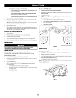
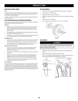
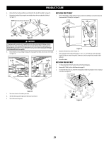
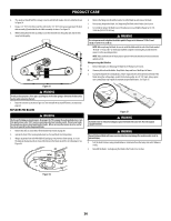
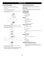
PRODUCT CARE 4. Remove the four lynch pins (a) that secure the deck to the deck lift assembly. See Figure 31. 5. Remove the lynch pin (b) securing the rear stabilizer bar to the rear, right side of the deck. See Figure 31. NOTE: Right side of mower deck shown (a) REPLACING THE PTO BELT 1. Remove the PTO belt (a) from the deck as instructed in the Deck Removal section then remove it from around the PTO clutch (b). See Figure 33. (c) (d) (b) (a) Figure 31 CAUTION The spring is under tension due to the weight of the deck. When removing the lift linkage from the deck the tension of the springs will go from the deck to the deck lift handle. Not capturing the deck height index by placing the clevis pin behind the lowest position while removing the lift linkage from the deck will cause it to snap back. 6. Remove the hex screws (a) flange lock nuts (b) securing the front deck control rods (c) to the deck. See Figure 32. (a, b) (c) (a, b) (c) (a) (e) (a) (b) Figure 33 2. Route the PTO belt (a) as shown in Figure 33. 3. After routing the belt around the PTO pulley (c), use a 1⁄2" (12.7 mm) drive in the idler pulley bracket (d) and turn towards the right of the mower to finish routing the belt around the idler pulley (e). 4. Reinstall the deck. REPLACING THE DECK BELT 1. Set the parking brake. Remove ignition key and both spark plug caps. 2. Remove the PTO belt, (refer to Deck Removal on page 24). 3. To remove the belt covers (a) , remove the wing knobs (b) from the carriage screws (c) securing it to the deck. See Figure 34. (a) (b) Figure 32 7. Turn front wheels as if to make a pivot turn. 8. Shift the deck toward the right side of the mower and remove. 9. To install reverse the process. (c) (c) (b) Figure 34 25
-
 1
1 -
2
-
3
-
4
-
5
-
6
-
7
-
8
-
9
-
10
-
11
-
12
-
13
-
14
-
15
-
16
-
17
-
18
-
19
-
 20
20 -
 21
21 -
 22
22 -
 23
23 -
 24
24 -
 25
25 -
 26
26 -
 27
27 -
 28
28 -
 29
29 -
 30
30 -
31
-
32
 |
 |
