Cub Cadet XT2 SLX50 FAB Operation Manual - Page 8
Installing the Front Bumper If equipped
 |
View all Cub Cadet XT2 SLX50 FAB manuals
Add to My Manuals
Save this manual to your list of manuals |
Page 8 highlights
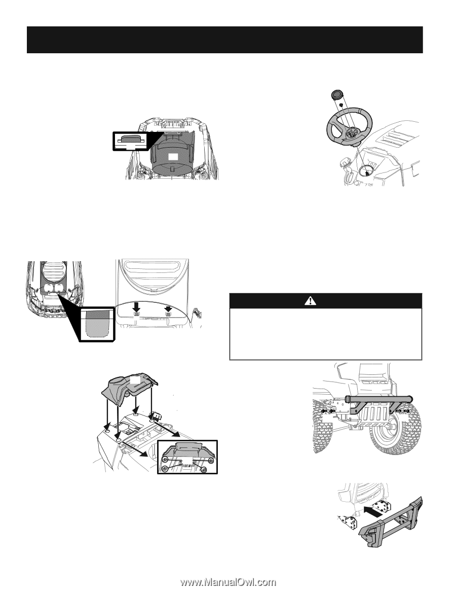
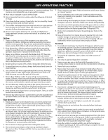
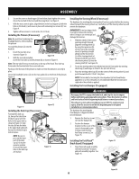
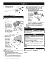
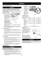
ASSEMBLY 2. Secure the screw-on hood topper (a) from below, hand-tighten the screws (b) on the rear half of the hood and then snug them. See Figure 9. 3. With the rear screws in place, align the holes in the hood topper (a) with the holes in the hood (c) and secure in place with remaining two screws (d). See Figure 9. 4. Tighten all four screws to 16-24 in-lbs (1.8-2.7 N-m). Installing the Plenum (If necessary) Note: Be careful not to damage the headlight harness when installing the plenum. (c) To install the plenum (a) onto the hood (b): (b) (a) 1. Insert the rear tabs (c) as shown in Figure 10. Figure 10 2. With the rear tabs installed, insert the front tabs (a) on the plenum (b) as shown in Figure 11. Note: The rear tabs fit into a recessed area on the top of the hood. They slide up from under the hood and into these recessed areas. Push up on the bottom of the plenum to make sure that the plenum is securely in place. Secure the headlight harness (a) into the two guides (b) on the front of the plenum. Figure 12. (b) (a) (a) (a) (a) (b) (b) Figure 11 Figure 12 Installing the Dash Cap (If necessary) To install the dash cap (a), line up the tabs (b) on (a) the dash cap (a) with the holes in the upper dash as shown in Figure 13. Slide the tabs (b) into the holes in the upper dash and push forward on the dash cap to lock into place. NOTE: Be sure to press on the lower part of the dash cap (a) facing the operator position to ensure the lower tabs on the dash cap are in place. (b) Figure 13 Installing the Steering Wheel (If necessary) The hardware for attaching the steering wheel has been packed within the steering wheel, beneath the steering wheel cap. Carefully pry off the steering wheel cap and remove the hardware. (f) IMPORTANT! Do not use impact tools to install or remove the steering (e) (b) wheel. Doing so can overtorque and damage the fastener. (a) 1. With the wheels of the tractor pointing straight forward, align the steering wheel (a) (c) by using the center-line (b) on the front of the steering wheel (a) pointing straight ahead and the flat section (c) of the steering wheel (a) facing toward the seat, place the steering wheel (a) over the steering shaft (d). See Figure 14. (d) Figure 14 2. Secure the steering wheel (a) with the hex bolt (e) from under the steering wheel cap (f) and torque to 18-22 ft.-lbs (24.4-29-8 N-m). 3. Place the steering wheel cap (f) over the center of the steering wheel (a) and push downward until it "clicks" into place. NOTE: The hex bolt (e) securing the steering wheel (a) has thread locker applied to it, so if it is removed, it is recommended that the hex bolt (a) be replaced or thread lock re-applied. Installing the Front Bumper (If equipped) WARNING Disengage the PTO, engage the brake lock, and stop the tractor engine before performing any preparation procedures. Place the tractor on a firm and level surface before beginning installation or removal procedures. The exhaust system and surrounding areas are HOT. To avoid personal injury, allow the tractor to cool before beginning any brush guard installation or removal procedures. The hardware for attaching the front bumper is shipped installed into the bumper. 1. Remove the four hex screws (b) (a) from the bumper (b). 2. Position the bumper brackets to the inside of the (a) (a) tractor's frame and secure it in place with the four hex flange screws (a). See Figure 15. Installing the FastAttach™ Brush Guard (If equipped) 1. Align the brush guard assembly with the FastAttach™ brackets and push assembly together. See Figure 16. Figure 15 Figure 16 8
-
 1
1 -
2
-
 3
3 -
 4
4 -
 5
5 -
 6
6 -
 7
7 -
 8
8 -
 9
9 -
 10
10 -
 11
11 -
 12
12 -
 13
13 -
14
-
15
-
16
-
17
-
18
-
19
-
20
-
21
-
22
-
23
-
24
-
25
-
26
-
27
-
28
-
29
-
30
-
31
-
32
-
33
-
34
-
35
-
36
-
37
-
38
-
39
-
40
-
41
-
42
-
43
-
44
-
45
-
46
-
47
-
48
-
49
-
50
-
51
-
52
-
53
-
54
-
55
-
56
-
57
-
58
-
59
-
60
-
61
-
62
-
63
-
64
-
65
-
66
-
67
-
68
-
69
-
70
-
71
-
72
 |
 |