Cub Cadet XT2 SLX54 Operation Manual - Page 22
Installing the Blade, Removing the Blades
 |
View all Cub Cadet XT2 SLX54 manuals
Add to My Manuals
Save this manual to your list of manuals |
Page 22 highlights
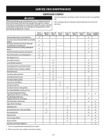
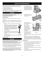
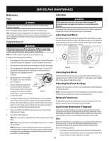
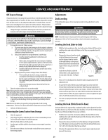
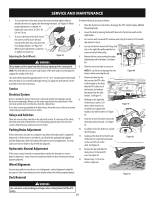
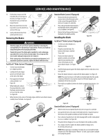
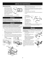
SERVICE AND MAINTENANCE 14. Pull the bow-tie pin out of the front deck lift rod securing it to the deck. See Figure 44. Slide the deck lift rod out of the front hanger bracket. 15. Move the deck lift lever into the top notch to raise the deck lift up and out of the way. 16. Gently slide the deck out from underneath the tractor. Removing the Blades Figure 44 WARNING • Shut the engine off and remove ignition key before removing the cutting blade(s) for sharpening or replacement. Protect your hands by using heavy gloves when grasping the blade. • Periodically inspect the blade and/or spindle for cracks or damage, especially after you've struck a foreign object. Do not operate the tractor until damaged components are replaced. • If the cutting edge of the blade has previously been sharpened, or if any metal separation is present, replace the blades with new ones. FastAttach™ Blade System (If Equipped) 1. Set the tractor deck height to its highest position. 2. Carefully feel for the finger grooves on the blade collar at the sides of the blade. 3. Push upward on the blade collar and hold it. See Figure 45. 4. While holding the collar in the upward position, rotate the blade counterclockwise to free it from the collar. See Figure 46. Figure 45 5. When the hole in the center of the blade aligns with the tractor blade retainer, carefully lower the blade. See Figure 47. Standard Blade System (If Equipped) 1. Remove the deck from beneath the tractor, (refer to Deck Removal earlier in this section) then gently flip the deck over to expose its underside. 2. Place a block of wood between the deck housing baffle and the cutting blade to act as a stabilizer. See Figure 48. 3. Remove the hex flange nut that secures the blade to the spindle assembly. Installing the Blade Figure 48 FastAttach™ Blade System (If Equipped) 1. Set the tractor deck height to its highest position. 2. Properly orient the blade. The bottom of the blade is labelled "Grass Side". 3. Position the blade under the spindle assembly, and carefully align the large opening in the center of the blade over the tractor blade retainer. See Figure 49. Figure 49 4. Push the blade upward against the blade adapter until the collar above rises. See Figure 45. 5. Rotate the blade clockwise to align with the blade adapter. See Figure 50. NOTE: If too much resistance is felt while turning the blade then the spindle is rotating, the blade is not properly aligned on the blade adapter, and installation will not be successful. 6. There will be an audible click when the blade is properly locked in place. See Figure 51. Figure 46 Figure 47 Figure 50 Figure 51 Standard Blade System (If Equipped) 1. With the deck removed gently flip the deck over to expose its underside. 2. Line up the the hole in the center of the blade with the s-shaped retainer at the bottom of the spindle assembly and slide the blade into place. 3. Place a block of wood between the deck housing baffle and the cutting blade to act as a stabilizer. See Figure 48. 4. Thread on the hex flange nut to secure the blade to the spindle assembly. 5. Use a torque wrench to tighten the blade spindle hex flange nut to 70 -90 ft-lbs (95-122 N-m). NOTE: When replacing or reinstalling the blade, be sure to install the blade with the side of the blade marked ''Bottom'' (or with a part number stamped in it) facing the ground. 22
-
 1
1 -
2
-
3
-
4
-
5
-
6
-
7
-
8
-
9
-
10
-
11
-
12
-
13
-
14
-
15
-
16
-
 17
17 -
 18
18 -
 19
19 -
 20
20 -
 21
21 -
 22
22 -
 23
23 -
 24
24 -
 25
25 -
 26
26 -
 27
27 -
28
-
29
-
30
-
31
-
32
-
33
-
34
-
35
-
36
-
37
-
38
-
39
-
40
-
41
-
42
-
43
-
44
-
45
-
46
-
47
-
48
-
49
-
50
-
51
-
52
-
53
-
54
-
55
-
56
-
57
-
58
-
59
-
60
-
61
-
62
-
63
-
64
-
65
-
66
-
67
-
68
-
69
-
70
-
71
-
72
 |
 |
