Cub Cadet ZTX6 60 Operation Manual - Page 7
Assembly
 |
View all Cub Cadet ZTX6 60 manuals
Add to My Manuals
Save this manual to your list of manuals |
Page 7 highlights
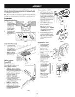
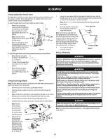
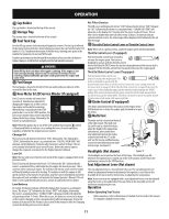
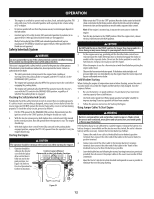
ASSEMBLY Note: This Operator's Manual covers several models. Tractor features may vary by model. Not all features in this manual are applicable to all tractor models and the tractor depicted may differ from yours. Note: All references in this manual to the left or right side and front or back of the tractor are from the operating position only. Exceptions, if any, will be specified. Preparation Manually Move the Tractor 1. To engage the transmission bypass rods, pull the rod back (a) and into lower section of "J" slot. Repeat on opposite side. See Figure 1. 2. After moving tractor, reverse step one to disengage the bypass rods. (a) (b) Install Hitch (If necessary) 1. Locate Hitch (a) and install on the rear of the frame using the two hex washer screws (b) provided. See Figure 2. Note: Hitch and hex washer screws will be the hardware pack. (a) Figure 1 Roll Over Protective System (ROPS) Refer to Figure 3 and the following descriptions and uses for the three (3) positions for the ROPS. • TRANSPORT: Only to be used when transporting the tractor or when they need to be momentarily folded-down to avoid contact with items such as tree limbs, clothes lines, guy wires, utility poles, buildings, etc. • TRANSPORT WITH BAGGER: Allows for the ROPS to be lowered for situations outlined for the TRANSPORT position when the tractor is equipped with a bagger. • OPERATION: The ROPS should always be in this position when operating unless the situations involved outlined in the TRANSPORT and TRANSPORT WITH BAGGER descriptions arise. (b) (b) Figure 2 Operation Position BaTgrgaenrsPpoosrittwiointh Transport Position Figure 3 To change the position of the ROPS: 2. pull slightly up on the upper ROPS to relieve any tension on the locking pin (a) and rotate the locking pin (a) from the LOCKED (b) position into the ADJUSTMENT (c) position. Repeat the procedure for the locking pin on the opposite side. See Figure 4. 3. Move the ROPS into the desired position. See Figure 5. Note: The three positions are TRANSPORT (a) position, TRANSPORT WITH BAGGER (b) position and into the OPERATION (c) position. 4. Rotate both locking pins into the LOCKED position. Move the upper ROPS slightly until the locking pins settle, engaged in the LOCKED position. (c) (b) (a) Figure 4 (b) (c) (a) Install Operator's Seat Figure 5 1. Cut any straps securing the seat assembly to the tractor. Remove all packing material. Note: Be careful not (b) to cut the seat wiring harness. (a) (b) 2. Install the seat onto (a) the seat pan (c) using hardware provided using (a) flange lock nuts (a) and flat washers (b). See (a) (c) Figure 6. Figure 6 3. If necessary, securely connect the seat switch wiring harness (b) (a) to the seat switch (b). See Figure 7. Secure excess wire (b) away from pinch points before (a) continuing. Note: Tractor will not operate without the seat switch wiring harness connected. (a) Figure 7 7
-
 1
1 -
 2
2 -
 3
3 -
 4
4 -
 5
5 -
 6
6 -
 7
7 -
 8
8 -
 9
9 -
 10
10 -
 11
11 -
 12
12 -
13
-
14
-
15
-
16
-
17
-
18
-
19
-
20
-
21
-
22
-
23
-
24
-
25
-
26
-
27
-
28
-
29
-
30
-
31
-
32
-
33
-
34
-
35
-
36
-
37
-
38
-
39
-
40
-
41
-
42
-
43
-
44
-
45
-
46
-
47
-
48
 |
 |
